Jockettino
Guest
Good morning to all,
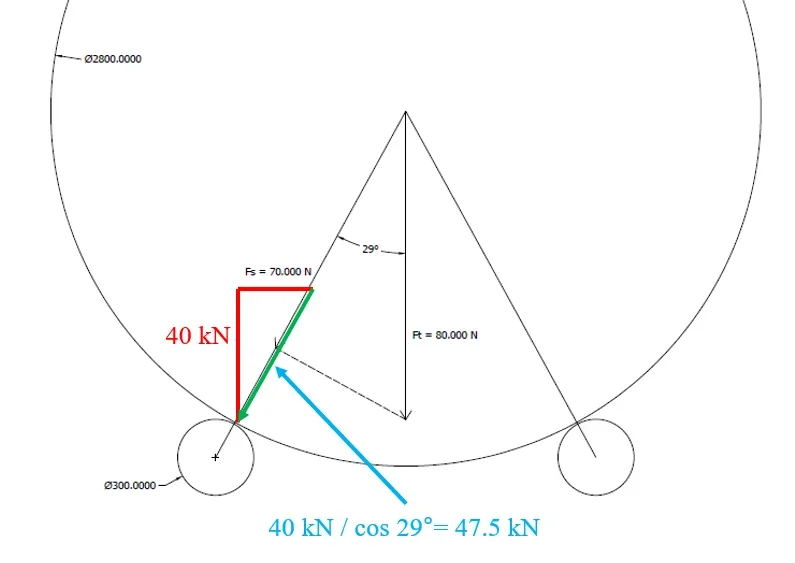
I am designing a rotary drum for the drying of the malt and I need your help to understand if I am correctly dimensionaling some elements. the drum has a diameter of 2800 mm and rests on two pairs of wheels. the total weight of the full load drum is about 16000 kg so each pair of wheels will support a weight of 80000 n.
as you can see from the attached sketch the wheels of the torque are at step 1500 mm between them and decomposing the forces I find that each wheel has a load of about 70000 n.
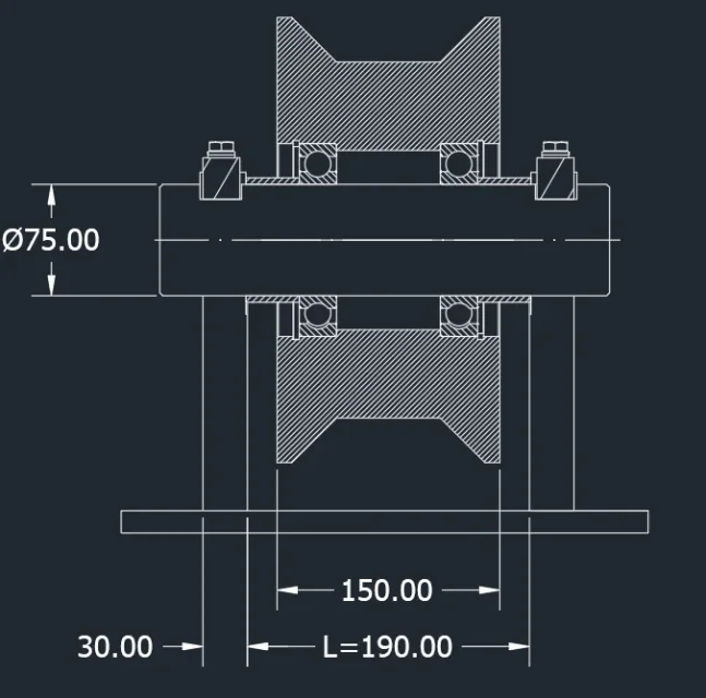
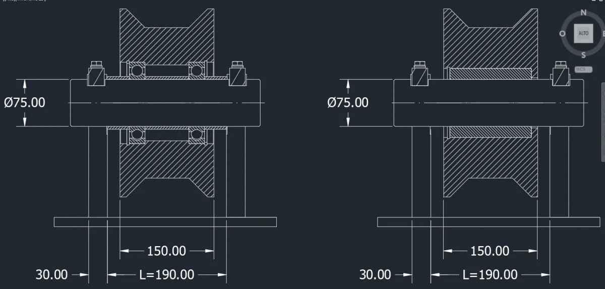
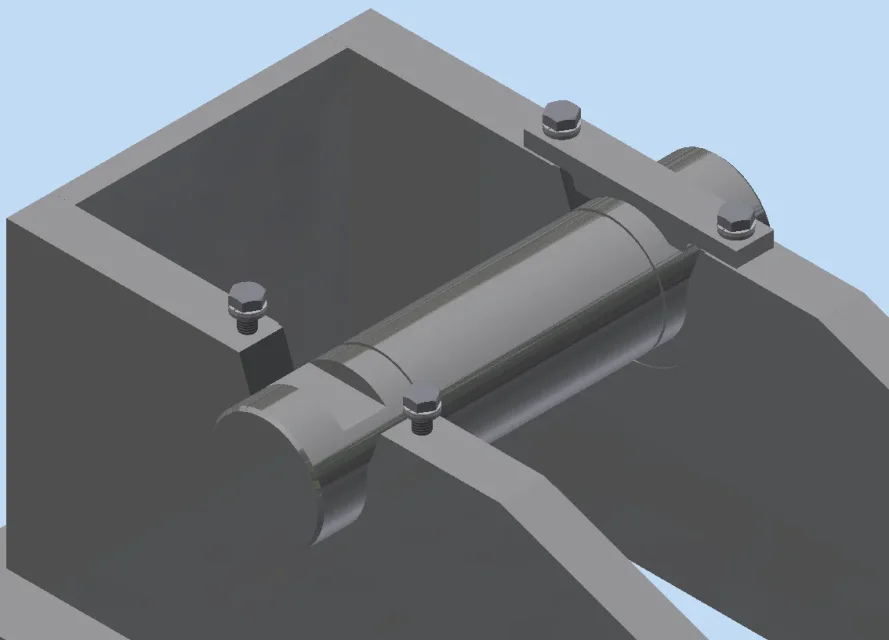
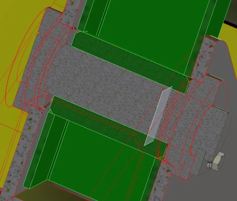
I attach my idea of wheel and pin, as you can see I have a pin to which I prevent the rotation on which I mount a wheel with a bronze stopped by a seger. The sketch has the final quotas derived from my accounts.
in this situation the pin is subject only to moment fs generated by force fs and with arm l/2. the pin I thought in c40 with a rm of 600 n/mm2 and a safety factor n=5. σamm = 120 n/mm2
with the bending pin sizing formulas results:
d=(32*mf)/(π*σamm)
d=(fs*l/2)/(π*σamm)
d=82.64 mm rolled to 85 mm
Whereas a l/d ratio of 1.5 is a 130 mm long bushing.
looking on the internet I found a commercial bronze bushing with dimensions ø85-ø100 l=130 mm.
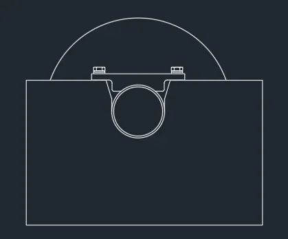
for the base of support of the wheels I thought of a welded box of iron plates sp 30 mm with machine tooling.
I'm pretty sure of the accounts I've done but I ask you to confirm that sometimes I'm going to fossilize things that I think I'm right and then I realize I've made a mistake completely.
Thank you.
Mar

