• This forum is the machine-generated translation of www.cad3d.it/forum1 - the Italian design community. Several terms are not translated correctly.

design with spaceclaim

  • Thread starter Thread starter SimoneDB
  • Start date Start date
Here's the video I promised you marco:[video=youtube;OuhdRGkszDc]https://www.youtube.com/watch?v=ouhdrgkszdc&feature=youtu.be[/video]
https://www.youtube.com/watch?v=ouhdrgkszdc&feature=youtu.be
thanks gorea, the video makes the idea good!
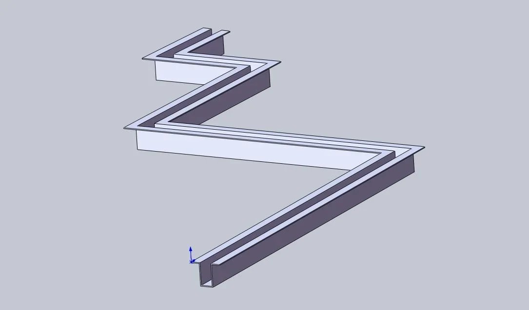
In my specific case I realized, with solidworks, an omega-shaped canal that follows an open linear profile dx-sx with angles of 90°, 88° and 86°. the problem I encountered with solidw is the overlap between the thicknesses (which does not happen with a profile like the video) and I was wondering if with spaceclaim I would have found the usual problems. . .
 
Maybe you mean that when you develop some faces, they're overlapping? It seems interesting to me the problem and I would like to know more. Is there an image of what happens? I feel so.
 
Maybe you mean that when you develop some faces, they're overlapping? It seems interesting to me the problem and I would like to know more. Is there an image of what happens? I feel so.
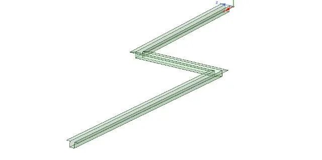
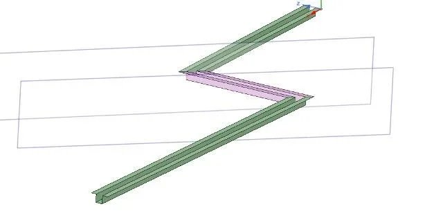
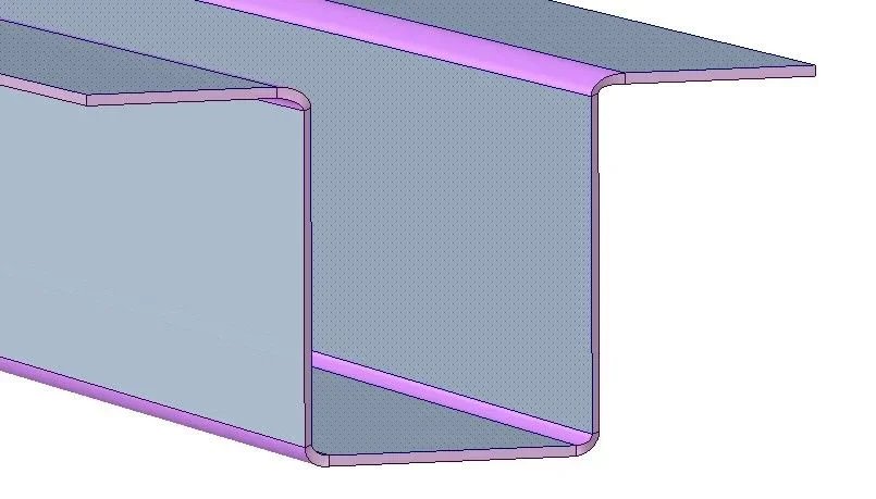
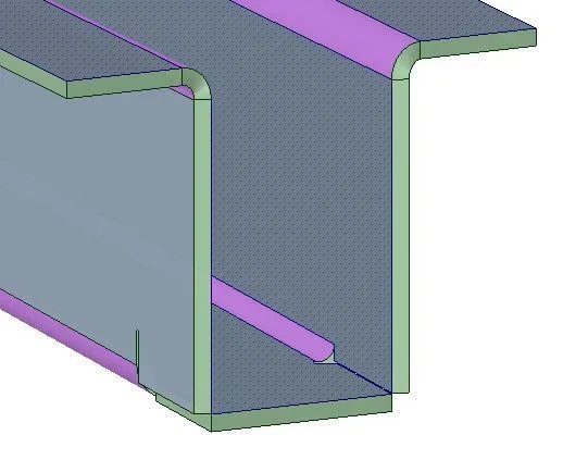
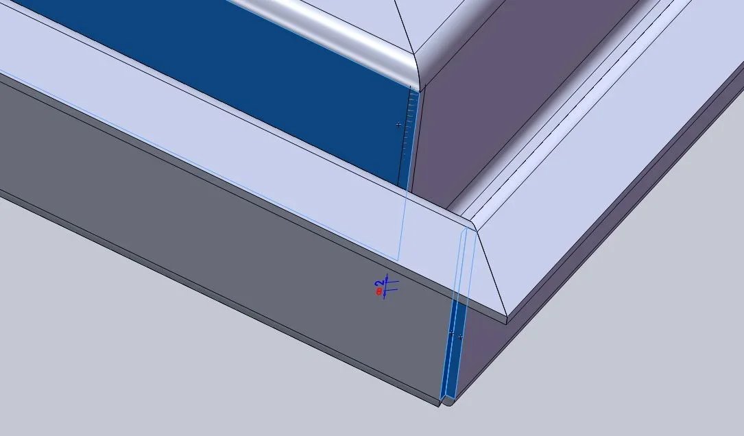
Here's some photos. .sweep.webp from here you can see the piece I made. .sweep1.webpsweep2.webp here it is seen that when converting from solid to sheet, and I dedicate the outer thickness, the result is a good side and one with surmounted thicknesses!

In my case, with solid, I solved creating a side file with an extruded cut and I mounted it in a file together. the result is that hoped.. .Assieme sweep.webpWhat I was asking is how spaceclaim behaves in these cases, by curiosity. do you have the same problems as solidworks?

thanks for the attention.
 
no, this problem is not there, but consider that I do not extrude the profile with the folds, but to live edge, the folds and welds I create them later. at each welding the software creates the joints (in bar, partial, or leaving the vacuum), and it is precisely in this phase that separates the parts leaving a minimum of margin (no overlaps).
 
no, this problem is not there, but consider that I do not extrude the profile with the folds, but to live edge, the folds and welds I create them later. at each welding the software creates the joints (in bar, partial, or leaving the vacuum), and it is precisely in this phase that separates the parts leaving a minimum of margin (no overlaps).
and in this case the discharges on the corners how they come? big or small and shaved like my last image? (I guess it's not the case that she had in mind before I sent her pictures, is it? )
perhaps this is a weak point of solidworks, but the best system (although slower) is to start from "lamiere" and not from solid or surfaces / extrudes / converts. in spaceclaim instead, to create this piece, what is the most profitable system?
 
no marco, more or less the example is that of the video, it changes little. the best strategy (in this case) is what I showed you.


The discharges come in some small cases, in other larger ones (however settable in the settings, but normally at least equal to indoor+thick radius). in some cases you can do them as you did (or in a very similar way) as I showed you in the video (the edges are yellow, and normally you can change them with one of the pre-existing forms).


If it had been a rectangle with 4 walls at the top, going on the outside (cut at 45° each with each other) and going down I would have drawn a rectangle, dragged the 4 edges up, outside, down and there would have been 10 seconds of watch (I do not make the video because it would last too little:d). in your case I would have used drag the profile along the guide, extrude solid surface, convert to sheet metal.
Hello andrea, I would have another curiosity: is it possible to configure a file in open and closed mode so that it can be recalled as desired in the context (as with sw configurations? ).
is also possible to buy at discounted price the old spaceclaim 2014?
thanks for the attention and good year.
 
Hello andrea, I would have another curiosity: is it possible to configure a file in open and closed mode so that it can be recalled as desired in the context (as with sw configurations? ).
is also possible to buy at discounted price the old spaceclaim 2014?
thanks for the attention and good year.
Hello, Marco.
I don't know solidworks specifically, but taking from the sw site the information about the set up I answer you.

First of all there is no assembly environment and a modeling environment, but a mixed environment, in which you can create a set even after creating the individual parts (this is the beauty of direct modeling!). you can change an item even in the axieme. you can save a single file that encloses together and its parts (also development and placing on the table), or save the parts as separate files. but you can also incorporate the "uniche" parts into the main file and insert the reusable components as external files.
overview of the configuration of parts and assemblies in solidworks:


1) quickly create "derived" versions of a project to speed up the creation of a different version
2) creation of configurations of parts by inserting, excluding and varying functions, odds and information displayed, based on simple items of a table
3) creation of axiemi configurations by inserting, excluding and varying parts, functions, odds and information displayed in the axieme, based on simple items of a table
4) Simplified or detailed creation of part project versions in the same file
5) creating a configuration for each phase through which a part passes during manufacturing (for example, casting, processing, welding, etc.)
6) creation of explosive versions of the assemblies to help explain the project
7) use of configuration publisher to prepare assemblies with multiple versions that will have to use other people
1)The various versions are saved (with a special new version rescue function). you can also make a comparison (markup) between the versions, so that you automatically color variations with different colors.
2)you can insert new parts, hide them, replace them. you can't act on the functions... because they don't exist!
3)As above, there is no distinction between what can be done in one part and together. I'm the same environment!
4)you can duplicate a set in the same file, turn off the original and change the copy making it independent
5)There are no processing
6)explosed version is connected to the project and to the table
7)From the point of view of the documentation of the new versions we use the markup3d that makes slides with a differentiated coloring on the variations of the project (dimensions, area, new elements...). From the point of view of file sharing, you can automatically export the compacted versions of a set, to transfer to a colleague a single file that contains everything!

No rotten, you can't sell "old" versions, but maybe we talk about it elsewhere.
 
Hello, Marco.

I don't know solidworks specifically, but taking from the sw site the information about the set up I answer you.


First of all there is no assembly environment and a modeling environment, but a mixed environment, in which you can create a set even after creating the individual parts (this is the beauty of direct modeling!). you can change an item even in the axieme. you can save a single file that encloses together and its parts (also development and placing on the table), or save the parts as separate files. but you can also incorporate the "uniche" parts into the main file and insert the reusable components as external files.


1)The various versions are saved (with a special new version rescue function). you can also make a comparison (markup) between the versions, so that you automatically color variations with different colors.

2)you can insert new parts, hide them, replace them. you can't act on the functions... because they don't exist!

3)As above, there is no distinction between what can be done in one part and together. I'm the same environment!

4)you can duplicate a set in the same file, turn off the original and change the copy making it independent

5)There are no processing

6)explosed version is connected to the project and to the table

7)From the point of view of the documentation of the new versions we use the markup3d that makes slides with a differentiated coloring on the variations of the project (dimensions, area, new elements...). From the point of view of file sharing, you can automatically export the compacted versions of a set, to transfer to a colleague a single file that contains everything!


No rotten, you can't sell "old" versions, but maybe we talk about it elsewhere.
Thank you for now, now I read everything!
 
Hello andrea, I would have another curiosity: is it possible to configure a file in open and closed mode so that it can be recalled as desired in the context (as with sw configurations? ).
what you ask is preorgative of parametric modelers, with which from a data table you automatically get all configurations of the same file saved internally etc.
as you see from the answers to andrea-overcam points 1-2-3-4-5-7 are not replicable between the two cads. are two different worlds.
 
what you ask is preorgative of parametric modelers, with which from a data table you automatically get all configurations of the same file saved internally etc.
as you see from the answers to andrea-overcam points 1-2-3-4-5-7 are not replicable between the two cads. are two different worlds.
I still didn't get to read carefully, but the fact that I wasn't parametric I just forgot!
 
Hello, Marco.
I don't know solidworks specifically, but taking from the sw site the information about the set up I answer you.

First of all there is no assembly environment and a modeling environment, but a mixed environment, in which you can create a set even after creating the individual parts (this is the beauty of direct modeling!). you can change an item even in the axieme. you can save a single file that encloses together and its parts (also development and placing on the table), or save the parts as separate files. but you can also incorporate the "uniche" parts into the main file and insert the reusable components as external files.


1)The various versions are saved (with a special new version rescue function). you can also make a comparison (markup) between the versions, so that you automatically color variations with different colors.
2)you can insert new parts, hide them, replace them. you can't act on the functions... because they don't exist!
3)As above, there is no distinction between what can be done in one part and together. I'm the same environment!
4)you can duplicate a set in the same file, turn off the original and change the copy making it independent
5)There are no processing
6)explosed version is connected to the project and to the table
7)From the point of view of the documentation of the new versions we use the markup3d that makes slides with a differentiated coloring on the variations of the project (dimensions, area, new elements...). From the point of view of file sharing, you can automatically export the compacted versions of a set, to transfer to a colleague a single file that contains everything!

No rotten, you can't sell "old" versions, but maybe we talk about it elsewhere.
I have another case to report that made me feel sorry in sw12.http://www.cad3d.it/forum1/threads/43502-problema-costruzione-canale-scolo?p=352491#post352491in this case would be feasible quickly the axieme?
Thank you.
 
It takes about 10 minutes.
phase 1:
draw the external section (the smaller one) and the path that must follow (loft or sweep with constant section, in spaceclaim is called blend). the outer surface is thus created.fase1.webpphase 2:
cut through floors the surface in 3 partsfase2.webpStep 3:
iron the central sections with the special function in dragging "pink edge". now we have 3 surfaces with non constant sectionsfase3.webpStage 4:
Since the thickness is 1.5mm, round the edges with radius 1.5mm on the interior, 3mm on the exterior (this can be done later in sheet metal, automatically, but I prefer to work on the surfaces and not on the solid in these cases).Capture.webpphase 5:
drag the surface of 1.5mm so you get the solid "lamiera" and then developCapture.webpif you have clear ideas is simple!! !
 
It takes about 10 minutes.
phase 1:
draw the external section (the smaller one) and the path that must follow (loft or sweep with constant section, in spaceclaim is called blend). the outer surface is thus created.View attachment 39516phase 2:
cut through floors the surface in 3 partsView attachment 39517Step 3:
iron the central sections with the special function in dragging "pink edge". now we have 3 surfaces with non constant sectionsView attachment 39518Stage 4:
Since the thickness is 1.5mm, round the edges with radius 1.5mm on the interior, 3mm on the exterior (this can be done later in sheet metal, automatically, but I prefer to work on the surfaces and not on the solid in these cases).View attachment 39519phase 5:
drag the surface of 1.5mm so you get the solid "lamiera" and then developView attachment 39520if you have clear ideas is simple!! !
thanks gorea, already from here it is understood that it is all very quick and practical. its solution is not exactly "correct", since there is no parallel floor to the upper surface at the junction point of the 3 pieces. I imagine however that, even performing in drawing as I say, it is all much faster than with solidworks (it is this that has "topped" me in drawing the model with sw12!!). However, for this specific case, a simplified solution can be acceptable to be adjusted during welding!
Thanks again, Marco.
 
what you ask is preorgative of parametric modelers, with which from a data table you automatically get all configurations of the same file saved internally etc.
to respond to marcof (which I had escaped :tongue:) spaceclaim is parametric. if anything is not a feature based (it does not carry out the operations carried out, which are therefore not mobilable), but it acts on the geometry as it is, and there are no processing (i.e. you cannot create relationships like "vite-foro part a-foro part b-rondella-dado". It is a parametric because not only once a cylinder is made I can change "directly" the diameter and length, but I can make such dimensions "parameters" (groups in spaceclaim) editable by table. then from a data table (group panel) edit the size and you get different configurations.
 
It takes about 10 minutes.
(cut)
if you have clear ideas is simple!! !
thanks gorea, already from here it is understood that it is all very quick and practical. its solution is not exactly "correct", since there is no parallel floor to the upper surface at the junction point of the 3 pieces. I imagine however that, even performing in drawing as I say, it is all much faster than with solidworks (it is this that has "topped" me in drawing the model with sw12!!). However, for this specific case, a simplified solution can be acceptable to be adjusted during welding!
Thanks again, Marco.
Well, the model that made gorea-overcam is not as sure as what you posted, with those joint work, discharges etc. It's a little more than a sketch.
it would be interesting to put this example of sheet modeling in the specific section of comparison between the various cads and see how users of the parametric and contextuals create the folded and developed model, as the changes are manageable, as time is done and how much you can change.
[mode provocazione ON]according to me in the changes that concern fixed parameters of that gutter, type angles between the three elements, lengths, sections measurements of the profiles or even shape changes of the sections of the profiles, a parametric burys any contextual.[mode provocazione OFF]:smile:
 
to respond to marcof (which I had escaped :tongue:) spaceclaim is parametric. if anything is not a feature based (it does not carry out the operations carried out, which are therefore not mobilable), but it acts on the geometry as it is, and there are no processing (i.e. you cannot create relationships like "vite-foro part a-foro part b-rondella-dado". It is a parametric because not only once a cylinder is made I can change "directly" the diameter and length, but I can make such dimensions "parameters" (groups in spaceclaim) editable by table. then from a data table (group panel) edit the size and you get different configurations.
I believe I have understood what the ability to change from "quote" of spaceclaim.
But I meant "parametric" in the sense of a "parametric cad", feature based, history based with annexes and connected (wins etc) and with all the prerogatives of modeling and modification that a context cad does not possess. of course it is also worth the opposite.
 
Yes, I understood, many (including me a few years ago) I thought spaceclaim was not "parametric", but then I repented. the bonds of asses are there. the correct terms you used are feature based or history based (which are the opposite of direct modeling), but in common use it is also called "parametric", although it is a wrong term.

However surely (and here I agree) it is easier to make the piece in sc than to change it once done everything changing section or path (even if I think sw would have difficulty if I changed from omega to double t). for this reason I said "it is simple if you have clear ideas" just because you are little, 10 minutes, but if you change totally section or route then better remake much of the job by taking 8 minutes instead of trying to change. Ultimately if you have to do with the same model to "reconfigure" better a "feature based", you put more to create it, but less to change it substantially. if you always have different models or you have to make small changes better a "direct modeling". clearly according to my opinion/experience.

p.s.: I used the method for surfaces (with its limits in the joints), but the work in the piece that put the bending machine (which is also called marco) I did not put them only because they seemed superfluous (but I am not a bending machine, so I might be wrong, heheheh! instead if I explain to you I learn something), not because they cannot be done. it takes 1-2 more minutes to make 1 of the 4 sections concerned. alternatively there is an alternative method, that is to leave a single solid and make cuts with sheet metal toolsmodifica lavorazioni.webp
 
Yes, I understood, many (including me a few years ago) I thought spaceclaim was not "parametric", but then I repented. the bonds of asses are there. the correct terms you used are feature based or history based (which are the opposite of direct modeling), but in common use it is also called "parametric", although it is a wrong term.
I mean the question in the sense that I think it meant marcof:

is it possible to activate or deactivate some work of the model? For example, an asola, a pocket, a pin, etc. in the "history based" always exists a suppression variable that allows selectively inhibiting all processing; Is there an equivalent in sc?
 

Forum statistics

Threads
44,997
Messages
339,767
Members
4
Latest member
ibt

Members online

No members online now.

Back
Top