• This forum is the machine-generated translation of www.cad3d.it/forum1 - the Italian design community. Several terms are not translated correctly.

design with spaceclaim

  • Thread starter Thread starter SimoneDB
  • Start date Start date
I ask if it is possible in the field cartilages that are not the standard ones in the properties: I explain... for each sheet file, I must indicate the treatment in the cartilage under the material. I don't find the right property and if I do one, then it just stays in that file.
Yes, but you can write straight into the cartiglio and automatically create its property in the drawing file.
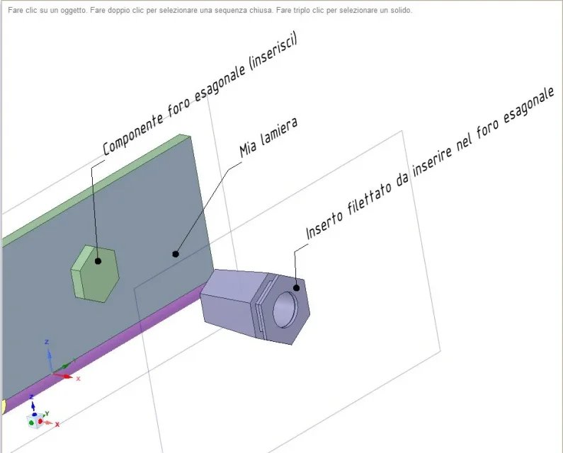
if I have to insert hexagonal thread inserts to pull, it takes a hexagonal hole for ognun insert: I made myself a hexagon-shaped component that they posiziono and then with comb, cut off the hexagon; inside the hexagon hole then, I put the insert. Is there any other way?
I'm not sure I understand. Do you want to create hexagonal holes? Did you try sheet metal with "forms"? There should be customized shapes, a click on the hole center and get the desired shape.
once made a custom table format, then when I make a table, can you no longer change? For example if the code field is too short because in the current case I have a longer code, how do I get it back into its space that I can't marry anymore?
no, I'm afraid not, the paper is editable only if you open it, not in the drawing sheet itself in real time... I don't think of any solution right now. I'll tell you!
 
Hi.

then for the first and third consideration, it is better not to put any features (apart from the date for example, which is not linked to the component) and to add as text directly in the folder... I deduce.

for the second:Inserto.webpin forms, I find only standard forms or bookshelf. He's not here. in the sheet there must be the hexagonal hole and then in the cartilage it is indicated that in that hole there must be pulled the insert. so I do so: insert in the project the hexagonal hole component for insert m5 (which I did); with the combination I make a subtraction and I pull the hole. then we hit the threaded insert with insert. to place others (e.g. another 20) I have to do a sketch in which for each insert I put a point and then with click control on each point... not really practical but you do.
strange that in a module for sheet metal there is no mention to threaded inserts.

Do you know any more tricks?

Hi.
Thank you.

Mar
 
I find it fast. . .
1) drawings a hexagon and the points in which to put others
2) in sketch mode with move and ctrl copy others to the desired points
3) with drag selections the first, and others with automatic selection tools (faces of the same area)
4) remove all hexagons dragging in negative.
View attachment inserti.zip
 
Bye-bye.

Yes, I see it as an alternative way. If I make a component with the right hole size (technical sheet name), I avoid reminding myself of the right diameter and the possible insertion error while I make it... but then the procedure is equal.

Thank you.
Hi.
 
Hello, Marco.
Yes, you can customize the tables of the separate base by adding component properties as:
Index
Name component
file name/path
quantity
xyz measurements
mass mass
volume
material (and other material properties)
custom fields (digitized in table and stored on the component)

In short, you can create more or less detailed boms, and with different custom models to recall when necessary.
andrea another curiosity: you can manage sheets with different thicknesses in a single set (only file) where for each sheet I have factor k and radius of different folds (with sw I usually do it..). Thank you.
 
Hi.

you can, see attached file.
I also do it habitually in sw though it is warmly not recommended... but I find it much more practical and faster.
in sc, just create new components to create within them all the different sheets you want. in a single file you have various components with inside one sheet... so much in sc there is no distinction between environment together and environment part... so it is as if in sw I made a sheet in every part and put the parts in a set.
View attachment Due lamiere.zip

ciao ciao
 
Hi.

you can, see attached file.
I also do it habitually in sw though it is warmly not recommended... but I find it much more practical and faster.
in sc, just create new components to create within them all the different sheets you want. in a single file you have various components with inside one sheet... so much in sc there is no distinction between environment together and environment part... so it is as if in sw I made a sheet in every part and put the parts in a set.
View attachment 45271

ciao ciao
Yes, you can have everything in a file, or a file that contains some internal components and others that point to other files (hybrid), or a "assieme" file and many component files. each component (inside or outside) can be sheet or not, and if sheet can have different properties (thickness, default radius, material, fold table or k factor).
 
Hi.

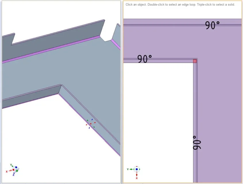
but how do you automatically solve the problem of the image below?Lamiera spigolo sovrapp.webpand why the command divides (to divide a folded leg far beyond the fold) always gives me error?
I see in some videos that with dividing, you can divide up beyond and then manage the two folds formed differently: in the videos for example one leave it at 90° and one stretch it and change the angle... I always make a mistake.

Hi.
Thank you.
Mar
 
Yes, you can have everything in a file, or a file that contains some internal components and others that point to other files (hybrid), or a "assieme" file and many component files. each component (inside or outside) can be sheet or not, and if sheet can have different properties (thickness, default radius, material, fold table or k factor).
Good then! like sw.
 
Hi.

you can, see attached file.
I also do it habitually in sw though it is warmly not recommended... but I find it much more practical and faster.
in sc, just create new components to create within them all the different sheets you want. in a single file you have various components with inside one sheet... so much in sc there is no distinction between environment together and environment part... so it is as if in sw I made a sheet in every part and put the parts in a set.
View attachment 45271

ciao ciao
I thank you for the answer, in fact I had come to mind also to me that could be a possible support for sc. I'm sorry that I can't see the file, I don't have a...
 
Hi.

but how do you automatically solve the problem of the image below?View attachment 45278and why the command divides (to divide a folded leg far beyond the fold) always gives me error?
I see in some videos that with dividing, you can divide up beyond and then manage the two folds formed differently: in the videos for example one leave it at 90° and one stretch it and change the angle... I always make a mistake.

Hi.
Thank you.
Mar
hi marco, sc, like any other program, you're right! when you open the piece by mistake because it is not feasible! I am a professional folder and I can tell you that in these cases I make a folded equilateral triangle halfway back on the piece after the fold. as second solution cut diagonally the piece and create the frame u in quatto pieces to reassemble in welding!

Hello, I hope I've been helpful! Let me know.
 
hi ps (piegatore solidworks :biggrin:),

Yes, I know that in solidworks you can do so, but I would like to know if in creation, there is a specific function that automatically (as there is for the frames) calculates the discharge for the two parts. even in sc you can do what you say... but I wanted to avoid manuals!
Andrea will know that.

Thank you.
Hi.
 
automatisms in this case are not there.
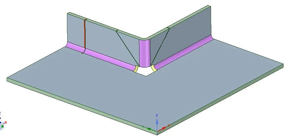
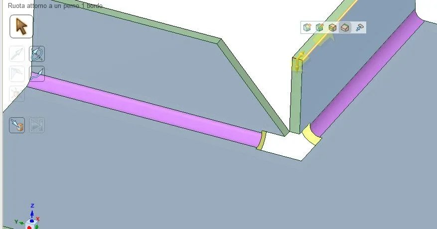
change the division between the two folded edges, drawings 2 lines to 45° and clicking on divides and then on the lines divide the excess part.dividi.webpalternatively dissociates the soldering (from purple becomes green), then with pivot board drags the necessary.bordo perno.webp
 
the rosss line instead shows the perpendicular division, useful if you want to divide a fold into two parts and one of them transform it into welding.
 
Good evening, I'm attacking this discussion, hoping someone will get it. (excuse the necroposting!). we use rhinoceros as cad, which I find very well seen the non-repeatability of the products.. About ten years ago, I was curious, but then between one thing and the other, I didn't get into it. I'd like to look back at this software that I've always been in my head. opening with a perhaps trivial question. . I remember that if you were drawing a piece and then you applied the series, going to the table the cartouche correctly reported the quantities of that element. sometimes it happened to have a set where in separate were repeated more 'positions of the same feature(identical).The question is: having n identical details (but not bound by a series) that are managed with separate positions on the cartiglio, it is possible to count them in separate positions in a single position? )I hope to have explained to me)
thanks in advance
 

Forum statistics

Threads
44,997
Messages
339,767
Members
4
Latest member
ibt

Members online

No members online now.

Back
Top