• This forum is the machine-generated translation of www.cad3d.it/forum1 - the Italian design community. Several terms are not translated correctly.

gas spring sizing

  • Thread starter Thread starter Luciano Ricci
  • Start date Start date
in the sense that the prevailing force is the one that makes the gas piston stretch. when the arms are disadvantageous to the piston, it fails to push enough and therefore contracts to win the forces at stake that are superior to its reaction. the push force is about constant of the piston. depending on the working geometry raises or lowers, pushes or pulls....but in the end he always pushes: so much or little in its range but physically it will never draw towards the center but yields.
 
in the sense that the prevailing force is the one that makes the gas piston stretch. when the arms are disadvantageous to the piston, it fails to push enough and therefore contracts to win the forces at stake that are superior to its reaction. the push force is about constant of the piston. depending on the working geometry raises or lowers, pushes or pulls....but in the end he always pushes: so much or little in its range but physically it will never draw towards the center but yields.
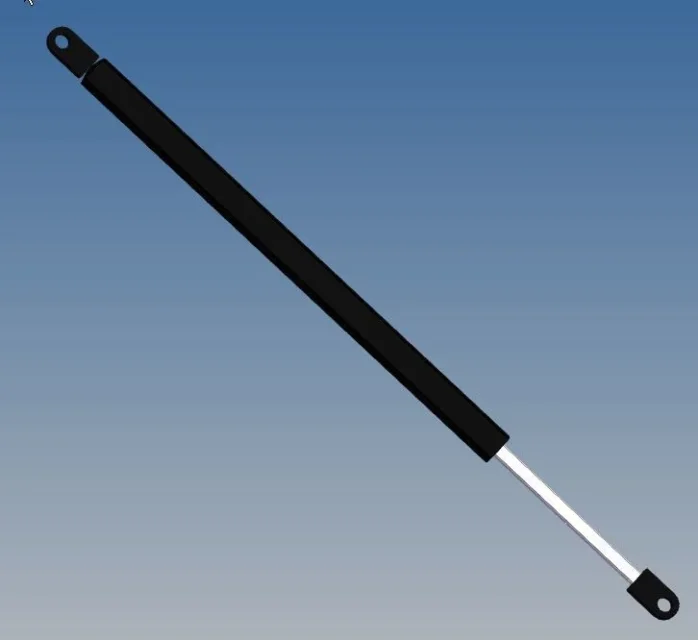
thank you very much for the explanation- I think I have grasped
 
I don't understand the phrase "they always paint to stretch"
I apologize if I have not read the whole discussion, but the phrase "they always paint to stretch" in my opinion simply means that it contains a compressed gas "late piston" so if it is not kept closed by some bond or force opposite the "gas spring" tends to open whatever its orientation.
some are wrong thinking that inverting the sense of a cilindo can change its behavior, instead when a cylinder works side piston opens, when working side stem closes.
returning to the gas springs their most classic behavior is like that of the rear hatch of a common 2-volume car: at the beginning when opening the hatch must be very tilted so that you can accompany it in the lifting phase, at the end instead the gas spring becomes almost vertical for having the force necessary to balance the weight of the hatch (obviously changing angle changes the vertical result of the thrust force).
you have to be careful not to push too strong the gas spring at the beginning otherwise the hatch opens onto you and of course at the end must result sufficient so that the moment of the gas spring is higher than the moment of the weight force of the hatch.
 
exactly. in fact the graphs of the cycles of the gas springs open and close, there is a minimum force and a maximum force but always in extension.
 
Hello, everyone.
by browsing a little the catalog of a producer I came across in the following difference:
http://www.stabilus.com/products/locking-gas-springs/bloc-o-lift-elastic-locking/
http:/www.stabilus.com/it/prodotti/...environ %2frk25252frk252frk 25252frs 2552fr -In summary here should make the difference between rigid and elastic block-o-lift, where elastic refers to the fact that when I go to release the button or lever, I have a shock absorber type effect while in the rigid case I have immediate locking without elastic shift.

Did I understand?
Thank you.
 
from the figure it is very well understood: one is a normal cylinder with beam hole between the rear and front chamber and here passes oil with slowing but not soaking nitrogen. the other does as the first but has extra nitrogen cushion that damps.
 
from the figure it is very well understood: one is a normal cylinder with beam hole between the rear and front chamber and here passes oil with slowing but not soaking nitrogen. the other does as the first but has extra nitrogen cushion that damps.
in practice the damping effect makes it the nitrogen cushion thanks to the valve placed in the head of the piston unlike the other where there is only one open-close.
correct?
 
Save to all, from the information of 2 gas springs manufacturers, it is recommended to prefer the assembly with the stem down, see attached image, to keep the seal seals wet from the oil and ensure the seal itself (avoiding so that the seal is dry and consequent oil leaks), this for "free" springs and also for springs with release.

There are also exceptions of gas springs (e.g. automatic release under instantaneous push for example) that should be installed on the contrary.
 

Attachments

  • molle.webp
    molle.webp
    7.4 KB · Views: 19
thanks for the info.
however there are cases and cases; For example I have seen gas springs mounted almost horizontally so the position of the stem seems to be "different".
 
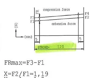
hello to everyone, I came across this diagram and there's something I miss.
In extension, (I release the piston key using the gas expansion) I run the section from f1 to f2; at the time of compression the f4 to f2 section.

I assume that in compression I need an f4 force greater than f2 to win the gas expansion as any friction. Is that correct?

fr must be the force of friction

I can't understand that x coefficient.

Am I wrong with something?

Thank you all.
 

Attachments

  • Cattura.webp
    Cattura.webp
    8.5 KB · Views: 36
x is the relationship between the force in push at the start of the race and at the end of the race. closer to 1 and more behavior is constant. It is normal that a gas spring push example 100kg completely extended to completely compressed pushes 90kg as there is a counterpression.
 
x is the relationship between the force in push at the start of the race and at the end of the race. closer to 1 and more behavior is constant. It is normal that a gas spring push example 100kg completely extended to completely compressed pushes 90kg as there is a counterpression.
Hello and thank you for the answer. the extension cycle should be from f2 to f1 while the compression cycle from f4 to f3. is correct?
in truth more than counterpression I had thought of the resistance that opposes the flow fluid in the cylinder
 
Why don't you take a serious catalog of gas springs where they show you the piston and its chart?
 
fact; in fact it is similar to what I attached to post #30
beyond stabilus and suspa you can recommend some catalog "serio": just to give a sense to graphical questions too.
Thank you so much for patience and availability!
 
Bye!
I looked at the site you suggested.
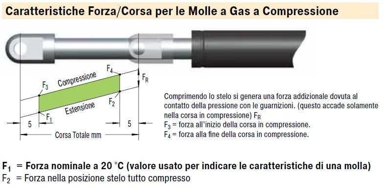
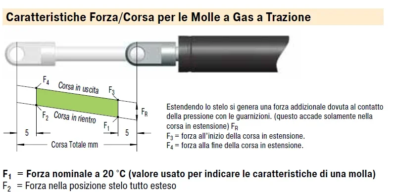
in the attached photo (the first) f2 should not be the force in a full-fledged position?

Am I confusing?
Thank you very much
 

Attachments

  • Cattura.webp
    Cattura.webp
    40.7 KB · Views: 36
  • Cattura2.webp
    Cattura2.webp
    38.6 KB · Views: 37
It seems to me that the two images above with a lot of caption in Italian are sufficiently explanatory. statically they maintain a constant value while dynamically they have a slightly different value.
 
It seems to me that the two images above with a lot of caption in Italian are sufficiently explanatory. statically they maintain a constant value while dynamically they have a slightly different value.
in summary, at the start of the extension I have f1 (at 5 mm run); As the gas chamber fills, the pressure increases in the chamber itself, for which, at equal stem diameter (and therefore area) the extension force increases as the race progresses.

:
 
Good morning, just to complete more or less the speech.. .

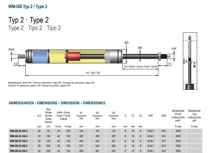
on the site of another manufacturer I found the attached image.
according to you a1, a2, a3 is the length indicated in figure to a certain % of the f1 force? !

thanks to all
 

Attachments

  • Cattura.webp
    Cattura.webp
    34.3 KB · Views: 41

Forum statistics

Threads
44,997
Messages
339,767
Members
4
Latest member
ibt

Members online

No members online now.
Back
Top