ValveFloyd
Guest
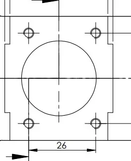
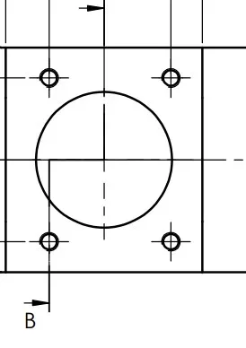
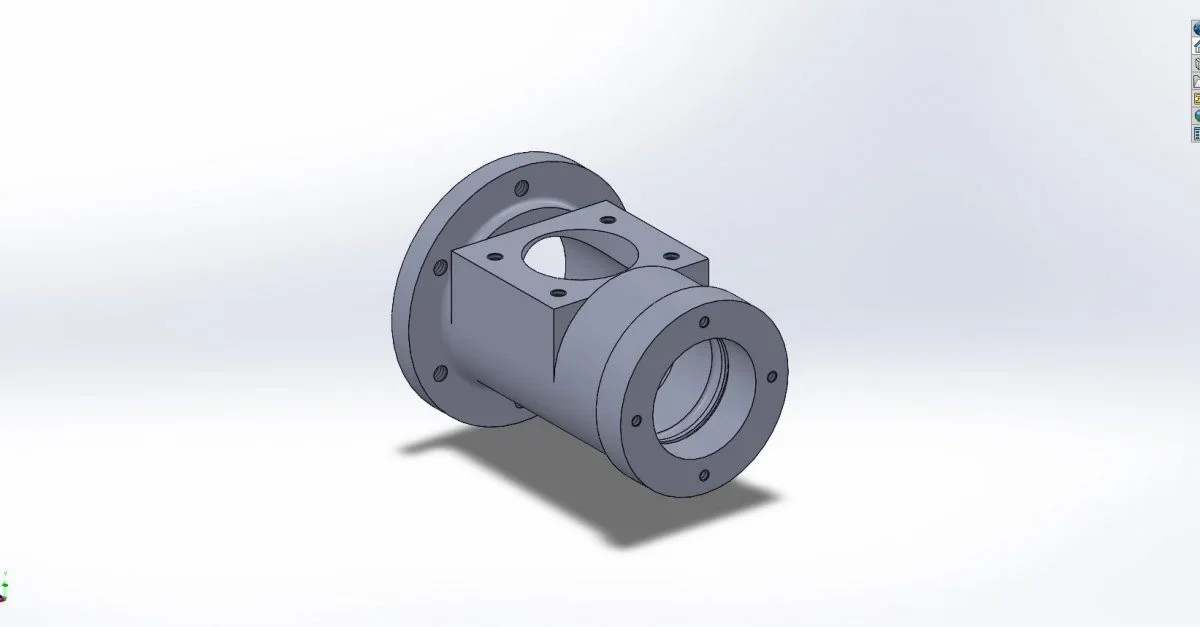
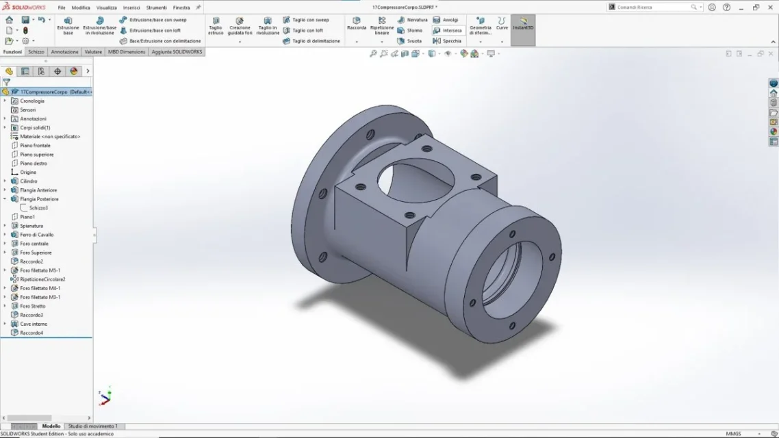
perfectly in agreement. in the drawings I published I sought a solution that was didactically correct, but that at the same time required the least number of views. this partly because I was taught this way, and partly because to the written test, especially for reasons of time, you must try to perform a complete solution with the minimum effort. I fully agree with the fact that it is an incorrect approach. I myself often find myself in difficulty interpreting overall (including what started the discussion), that although correct, for a beginner eye like mine, they are ostic without a large number of views. For example, recentmete I have realized the putting into the table of the body of this compressor, and to me it turns out that both interpretations I have made are correct (geometrially, then it is clear that one is more stupid than the other). What do you think?As a general advice, I think it's better not to tie up with the views... trying to stay in the smallest sheet format possible is a legacy of the past, when drawing to the tecnigraph. now with the cad the views come out in a second, so try to provide all the possible geometric information, to avoid misunderstandings. rather reduce the scale. in the base for example, I would add a view projected to the left, to show well the shape of the exhaust milling that is below and a view projected above to show that the milling 51.5 is completely passing (or not). In support I find both a forcing the view from b... there for there I thought of an American overturn. . only after I saw the arrow b. use a larger sheet and make normal projection if you can. the holes at 120° better if you put the coordinate quotas. Finally missing the general ruogosita, which usually puts on the cartilage.
for the rest, roughness, etc... I've noticed everything, and thank you very much.
p.s.
even here there are wrinkles and even a tide of fittings. I know that I should correct them before I publish them, but having little time I prefer to start something new so as to train even in reading, rather than revising all the drawings I did. Obviously if I have to load other jobs I will try to cure them as much as possible.