MassiVonWeizen
Guest
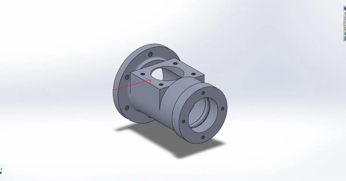
But why don't you cut 42 by? at the end what remains of the diameter you go to work, 1,2mm material? What do you need to do that fried?
By the way, you can't get the processing that you've represented at a live edge, but it must have the radius of the cutter that will be at least 5mm, making the processing useless.
edit added image
By the way, you can't get the processing that you've represented at a live edge, but it must have the radius of the cutter that will be at least 5mm, making the processing useless.
edit added image
Last edited: