• This forum is the machine-generated translation of www.cad3d.it/forum1 - the Italian design community. Several terms are not translated correctly.

roototrallatric coclea

anonto

Guest
Hello everyone,
I'm a mechanical engineering student and I'm going to revert a coclee until I get a model I can use for simulations in my graduation.View attachment 378the coclea in question (photo), coupled with his twin (specular), takes the product from a line (right), separates it from the line and rototrasla (also with the help of a lower tape) and finally translates it only (to the left).
the product is a rectangular prism, and enters between the two screws slightly inclined to favor separation

To replicate the piece, I thought I'd split the piece into three parts, the first and the last one more or less managed to do it, not without big doubt and perplexity:
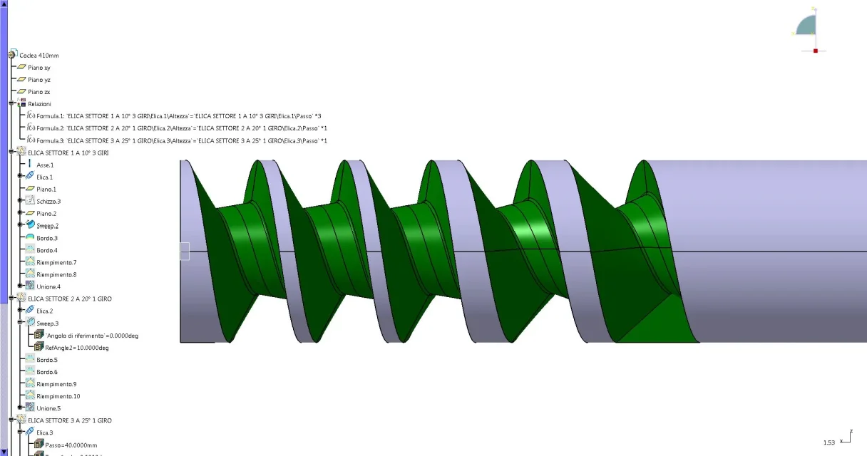
  • As for the first part (separation from the line) I drew a spiral with 3 different steps for 3 revolutions on the surface of the cylinder and carried out a sweep of the solid (not rotated, then with the long side almost parallel to the axis of the axle).
    coclea_inizio_seghetta.webpI discovered later (after several imprecations) that if the spiral is not centered on the tool outside those malice artifacts, moving the spiral on the center of the tool (no longer on the surface of the cochlea) I get a more realistic geometry:
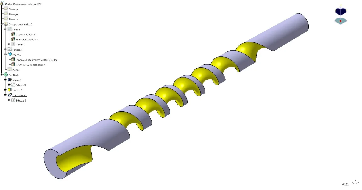
    View attachment 2899
  • for the final part (only translation) I always made a solid cut-sweep
    I initially tried with a cut-sweep of the solid in question rotated of 90 degrees (then the step is inferior), but the result does not represent the reality' (though it follows the indications that there are in the mega-thread on the extrusion of the
    coclea_sbagliata.webpare then passed to a cut-sweep following a fairly invented profile:
    coclea_piu_o_meno.webp
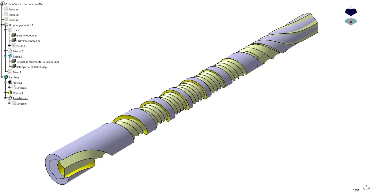
It's not very accurate, but you should do your job.
and now my drama:
the central part of the auger to rotate the piece I have absolutely no ideas on how to reproduce it.
exists a way to tell the tool (solid) that must follow a trajectory along a spiral, but which must also rotate in the meantime?

other questions, but not so serious and/or important, all about the first part of the cochlea:
the cut sweep seems not to go on if after 360 degrees the tool touches the track of the turn before, blocking the cut some degree before (not finishing the revolution then). Is there a way to bypass this limit? the actual coclea has the diameter cut for this reason.
solving the question before, is it possible to give the spiral a growing step without having to give it "discreetly"?
Finally, it is possible to indicate to swx a second direction for the spiral in order to have an extrusion also on the other side to "complete" the coclee?

thanks for any answers
Good day
 
Hello everyone,
I'm a mechanical engineering student and I'm going to revert a coclee until I get a model I can use for simulations in my graduation.View attachment 34798the coclea in question (photo), coupled with his twin (specular), takes the product from a line (right), separates it from the line and rototrasla (also with the help of a lower tape) and finally translates it only (to the left).
the product is a rectangular prism, and enters between the two screws slightly inclined to favor separation
(cutton)
and now my drama:
the central part of the auger to rotate the piece I have absolutely no ideas on how to reproduce it.
exists a way to tell the tool (solid) that must follow a trajectory along a spiral, but which must also rotate in the meantime?
no, and I imagine you have already searched several times and with the magnifying lens in the options of the solid sweep command to see that, alas, there is no chance to do what you ask.
If I were in your place, but only threatened by armed hand and having to start modeling immediately that excavation I would build the surface that corresponds to the volume occupied by the piece transported during the rotation. I would work together, placing a series of prisms at regular intervals throughout the central cochlea stretch along the respective spiral. For example, if the central part of the coclea is composed of two turns in which the piece performs a rotation of 180° positionrei 9 prisms ciscuno rotated of 20° and arranged at regular intervals along the two spiral turns to reproduce the 9 positions that the prism will have to assume along the rototranslation.
after, and here comes the beautiful, I would try to build the surfaces (of loft?) that pass for each edge of the prism during rotation , surfaces that by force must be joined, and that I would use later to cut the cochlea in the cylinder.
so on two feet with a cad I see no other solution. Perhaps, but I throw it there, with a 5-axis cam you could program the movement of the tool, make the simulation of the working of the whole coclea and export in iges the result of the simulation.
Here... I hope with this "help" (the quotes are obligatory) that you will not get more nightmares than you will already have to do this cochlea :redface:


other questions, but not so serious and/or important, all about the first part of the cochlea:
the cut sweep seems not to go on if after 360 degrees the tool touches the track of the turn before, blocking the cut some degree before (not finishing the revolution then). Is there a way to bypass this limit? the actual coclea has the diameter cut for this reason.
here I did not understand, or rather I did not understand why the tool should touch the track of the previous round; In that way, the whole spun of the newly created screws would be cut and I don't see the usefulness. I don't even know what you mean by the bold phrase
solving the question before, is it possible to give the spiral a growing step without having to give it "discreetly"?
If you need the starting step and the arrival step you can only give those two parameters as unique input data, but alemno those you will have to give them. after you choose the option "height and step", "height and revolution" or "pass and revolution according to your needs.
If the step changes differently along the spiral then you will have to insert one or more intermediate points.

Finally, it is possible to indicate to swx a second direction for the spiral in order to have an extrusion also on the other side to "complete" the coclee?
within the spiral command the direction you can set is unique, but also here I do not understand. Why would you need to have a definite spiral starting from a circle in its half (spiral that goes so in two directions) rather than a circle at the base or at the top?
 
but the twist of the section along the path is not enough? I don't understand anything.
 
but the twist of the section along the path is not enough? I don't understand anything.
"anont" wants to do the sweep excavation with the solid, not with the profile, and in the excavation with the solid there is no option for the torsion along the path, if it is the type of torsion that serves him
 
hello marcof and thank you for the answer.
I fear that the armed threat is not literal, but if I want to take that piece of paper I have to get out of it, and this is only the first step (!!!).
I would work together, placing a series of prisms at regular intervals throughout the central cochlea stretch along the respective spiral. For example, if the central part of the coclea is composed of two turns in which the piece performs a rotation of 180° positionrei 9 prisms ciscuno rotated of 20° and arranged at regular intervals along the two spiral turns to reproduce the 9 positions that the prism will have to assume along the rototranslation.
Okay, so far all clear and feasible - maybe - with my current knowledge, let's see if I understood correctly:
the piece rotates 90°, therefore I create 9 prisms, each rotated 10° and I place them along the trajectory that would assume if the coclea was firm and the piece rounded them.
after, and here comes the beautiful, I would try to build the surfaces (of loft?) that pass for each edge of the prism during rotation , surfaces that by force must be joined, and that I would use later to cut the cochlea in the cylinder.
I lost here.
once you create the 9 projections of the piece I have to create a unique surface that is tangent to all 9 projections (right?), and I do not know how to do, but I will inform myself.
and once you create this surface? Do I have to "take" it to the base cylinder?

I'll be informed about cam software, thanks for the tip.
the actual coclea has the diameter cut for this reason.
here I did not understand, or rather I did not understand why the tool should touch the track of the previous round; In that way, the whole spun of the newly created screws would be cut and I don't see the usefulness. I don't even know what you mean by the bold phrase
you can't see well from the photo, but the coclea in the first right revolution does not have the ridge (or shore, I don't know exactly what is called the unworked material on the outer diameter). The reason I think it's pure processing, and I don't think it affects the behaviour of the cochlea more than that. even if there is some difference with reality what interests me is the mechanism.

What about the step are you telling me that swx automatically changes it? then something smart does it!

Finally, the reason I need a spiral that goes also "back" is visible in the third image I posted. we see the starting point working well, while in reality it does not exist.
I think you can fix it by starting the spiral first, but then I don't know if you accept the cut.

to respond to re_solidworks, I am using a solid cut that rotates during the cut.

a couple of ignorant questions:
- to define the trajectory of a solid cannot indicate two curves, presumably? Not even for an extrusion?
example:
imposed the trajectory of the top-left corner of a plate with a straight; and the trajectory of the bottom-right corner of the same plate with a spiral.
If you can do such a thing, can I use what comes out to cut my base cylinder?

- is it possible to carry out work on a floor and then to "explain" the plan to form the cylinder? would be an activable solution?

thanks to both, good day
 
mike1967, I don't know if you're spying on me, but the coclea I'm reversing is from that company.
rs4 I can't agree with you anymore. a similar specialization brings money and work.

for marcof, I can't edit the post, but tonight I thought and thought about your solution, and it doesn't come back.
I'm afraid that using the surface of the piece to create the profile on the cylinder I'd get a "shaded" and uncontinuous piece.
Wouldn't it be better to try to reproduce a dozen profiles from the real augmentation, loft those and then use them to cut (I don't know how) the cylinder?
I'll explain better. I know that the coclee I have in my hand works. I know that the current geometry of the auger works. with a little effort I could take the profile measurements along the spiral. from which with a loft I could try to reproduce the spiral.
Where am I wrong?
 
for marcof, I can't edit the post, but tonight I thought and rethink your solution
Soccia... I did a lot of damage. worse than twenty cups of coffee :smile:

And it doesn't come back.
I'm afraid that using the surface of the piece to create the profile on the cylinder I'd get a "shaded" and uncontinuous piece.
I wrote to create the surface to be subtracted to the cylinder not using the surface of the piece to be translated but its edges that theoretically translating precisely along some surface, surface that could be derived from a loft between the various sections of maximum encumbrance of that piece taken in various steps along the translation.
Wouldn't it be better to try to reproduce a dozen profiles from the real augmentation, loft those and then use them to cut (I don't know how) the cylinder?
I'll explain better. I know that the coclee I have in my hand works. I know that the current geometry of the auger works. with a little effort I could take the profile measurements along the spiral. from which with a loft I could try to reproduce the spiral.
Where am I wrong?
but so you would reverse a bit at the kilo, I think. If you need to reporize a 3d model, you should use the translation surfaces generated by the encumbrance of your component that passes into the cochlea.
finding those surfaces is another pair of sleeves. mine was a "jet" suggestion so it can be very good to be unrealizable.

a question: but did you try to contact the company that produces those screws to understand with which tools they design them? I would not want them to be frescoed designed as 3d models but they were the result of the processing of dedicated cn machines, such as those to rectify/build the helical cutters where relatively few parameters are introduced and the complex surfaces resulting are "simplely" the fruit of the combined movements of a disc grinding wheel around a metal cylinder.
 
20 coffees, maybe not, but a dozen of them all more a big bunch, even because after the answer last night at 10:00:30, all I did was wait till the morning came to get back to the office.

you are right, the reverse would be very gross, but the real profile perfectly follows the course of the piece, it seems for the fact that they used a cn machine that "simple" the rotation of the piece.
I have already tried to contact the company, and told me that they use cam programs by inserting variables, steps and motion laws directly into the software and that they do not have 3d models to use.

do you want to read my first answer and clarify those two or three ( thousand) doubts?

Thanks again, good evening
 
mike1967, I don't know if you're spying on me, but the coclea I'm reversing is from that company.
rs4 I can't agree with you anymore. a similar specialization brings money and work.

for marcof, I can't edit the post, but tonight I thought and thought about your solution, and it doesn't come back.
I'm afraid that using the surface of the piece to create the profile on the cylinder I'd get a "shaded" and uncontinuous piece.
Wouldn't it be better to try to reproduce a dozen profiles from the real augmentation, loft those and then use them to cut (I don't know how) the cylinder?
I'll explain better. I know that the coclee I have in my hand works. I know that the current geometry of the auger works. with a little effort I could take the profile measurements along the spiral. from which with a loft I could try to reproduce the spiral.
Where am I wrong?
No, don't worry. . He thinks that this site made me know my partner, with him we share
passion for mechanics and things "strane".
I hope you can in your project, it's a great challenge.
 
I have already tried to contact the company, and told me that they use cam programs by inserting variables, steps and motion laws directly into the software and that they do not have 3d models to use.

as I suspected. . .

do you want to read my first answer and clarify those two or three ( thousand) doubts?
I read the first answer, but to clarify your doubts I should not have mine! :redface:
I see it hard, hard, any cad you have at your disposal. Perhaps because I use little surfaces and I try to imagine an effective procedure to reconstruct the volume occupied by that component during the translation. the solution would be precisely the sweep of a solid that had much more controls than those available to be able to set the rotation of the object according to certain rules.
iho or solve the thing in a numerical way, calculating (I don't know how) the points of the various curves of the coclea in order to reconstruct them on swx with the function "curve through the points" and to do so the relative surfaces, or I think that going of direct modeling is almost impossible to build something realistic. or you know where the various sections of the coclea are and how they are done (and why they are made like that) or imho is a lost race.
if the task is to study the movement within a more complex machine and not to make 3d modeling you should find a pious soul that makes you a reverse as you must with a scanlaser and thus have the file step of that auger. Obviously you forget about the changes, and if you need to check the operation of the screw with various parameters you are back on foot.
 
All right, now I'm officially desperate.
I would need the changes, especially to develop the thesis, so I don't know how much it can help.

So the possible (even certain) solutions I have are:
- discuss the positions of the piece along the spiral, create a tangent of negligible thickness, join them
- by analytical (why not by measurements?) I echo the points of the coclea, then I create a curve passing for such points and then I join the various curves with different surfaces, if I understood well
- find and learn a cam software with which you can simulate the movement of the piece and the coclee and export the 3d

as conclusion of each of these solutions, given insecurity, there is a "and see the effect it does"

Do you know any cam software that I can then use to export the coclea and use it on swx?

really nice anyway, is there a way to support the community?
 
I played a little with the v5 cat. I liked it.

revolution + conical and groove reform using direction of sweep

sweep with reference surface using law

allego img and step files
 

Attachments

  • Coclea Conica rototraslatrice RS4.webp
    Coclea Conica rototraslatrice RS4.webp
    61.1 KB · Views: 37
  • Coclea Conica rototraslatrice RS4.7z
    Coclea Conica rototraslatrice RS4.7z
    784.5 KB · Views: 17
  • Coclea Conica rototraslatrice sweep.webp
    Coclea Conica rototraslatrice sweep.webp
    81.6 KB · Views: 33
All right, now I'm officially desperate.
see it like this: at least start from something certain and know what to aim for:redface:
I would need the changes, especially to develop the thesis, so I don't know how much it can help.
then you have to discard both scanning and building for measuring points or analytical. to any modification of the coclea you want to test you must remake all the process of modeling from head to aprtire from the curves. with a parametric cad is a countersenso. you need to find the pole of the matax or find a much more sophisticated cad that allows for greater control on the surfaces. take into account that in that infamous thread on the helical excavation of a few years ago basically all the cads excavated the result of the sweep...

So the possible (even certain) solutions I have are:
(cut)
- find and learn a cam software with which you can simulate the movement of the piece and the coclee and export the 3d
I believe that with the cam you can (maybe) get the step of a cut piece according to a certain tool path. the difficulty could, anci it is, to determine (make an example) what is the diameter of the candle cutter and according to which path to turn it along the rough cylinder to obtain the coclea that contains a prism with section 10x20. The hard rivet...
the only cam that could obtain the imprint of a solid that translates into another changing orientation is that of the machines for electro-erosion, but I doubt that there are machines that can work to 4 axes a cylinder. try to ask anyway in the cam section or link there this discussion.

also with the cam imane the string to change the parameters of the coclea for your verifications/simulations to the cad by making every time the tool path.
really nice anyway, is there a way to support the community?
Sure! participate by giving a hand where you can do it.
 
I played a little with the v5 cat. I liked it.
revolution + conical and groove reform using direction of sweep
sweep with reference surface using law
allego img and step files
interesting, but I don't understand if that auger can do the rototranslation and what form he can do.
you can explain how to achieve the profile of that core starting from the project data: turn 90° a section prism tot1 x tot2 translating it of tot3 mm in tot4 turns (anont, provide this data with precision so that who does it with knowledge of cause). Maybe "anont" can have a caia and solve its problems.
I also shot a little bit with swx (depending on a residue of acute intoxication by helical excavation :rolleyes: and when the time changes I have some falls) but I am aborn mid loft, when the section of prisms begins to become almost perpendicular to the crank of the cylinder. I don't know how to move forward, I tried to do the intersection of prisms with vertical planes first in one verse then in the other (red sketch) but the loft that comes out, if I go beyond what you see in the video, it's fucked up.
Maybe it can be a track for "anxiety" to get some good ideas out of it. I also attach the swx files
View attachment coclea rototraslante.rar
[youtube]xbm2frw4oqw[/youtube]
 
I'll check if there's a version of the available casket to test with.
the size of the prism are:
width: 35 mm
depth: 15 mm
height: 60 mm

the screw is 410 mm long, 65 mm in diameter.

in the photo you see the various steps of the prism through the coclea.new_3.webpthe piece enters with a 10° angle and is rotated 90°.
the first 3 revolutions and the last 3 do not actually rotate the piece, which then rotates in 150 mm (but this size is not of fundamental importance) in 5 turns.
if they can serve I also took the measurements of each step (the ones marked on the sheet of the photos before), but I left them in the office :confused:

tomorrow or Monday I will take a photo with both screws in action in case this is not clear enough.

I just hope I don't become helix-dependent, marcof did you know if there are rehabilitation centres?
 
interesting, but I don't understand if that auger can do the rototranslation and what form he can do.
you can explain how to achieve the profile of that core starting from the project data: turn 90° a section prism tot1 x tot2 translating it of tot3 mm in tot4 turns (anont, provide this data with precision so that who does it with knowledge of cause). Maybe "anont" can have a caia and solve its problems.
I also shot a little bit with swx (depending on a residue of acute intoxication by helical excavation :rolleyes: and when the time changes I have some falls) but I am aborn mid loft, when the section of prisms begins to become almost perpendicular to the crank of the cylinder. I don't know how to move forward, I tried to do the intersection of prisms with vertical planes first in one verse then in the other (red sketch) but the loft that comes out, if I go beyond what you see in the video, it's fucked up.
Maybe it can be a track for "anxiety" to get some good ideas out of it. I also attach the swx files
View attachment 34826
[youtube]xbm2frw4oqw[/youtube]
hi marco was only to make anonto understand a possible solution in sw.. similar to catia as point, so not studied and really usable... for handling
 
I'll check if there's a version of the available casket to test with.
the size of the prism are:
width: 35 mm
depth: 15 mm
height: 60 mm

the screw is 410 mm long, 65 mm in diameter.

in the photo you see the various steps of the prism through the coclea.View attachment 34827the piece enters with a 10° angle and is rotated 90°.
the first 3 revolutions and the last 3 do not actually rotate the piece, which then rotates in 150 mm (but this size is not of fundamental importance) in 5 turns.
if they can serve I also took the measurements of each step (the ones marked on the sheet of the photos before), but I left them in the office :confused:

tomorrow or Monday I will take a photo with both screws in action in case this is not clear enough.

I just hope I don't become helix-dependent, marcof did you know if there are rehabilitation centres?
work in progres... I'm working for you...

I'll put you in
 

Attachments

  • work in progress.webp
    work in progress.webp
    106.1 KB · Views: 47
work in progres... I'm working for you...
I'll put you in
Does it seem to me or any of the two faces of the cochlea are perpendicular to the bottom? in the central part of the original cochlea one of the two faces (tools the fittings) is always perpendicular to the bottom and the other has a angle greater than 90°.
What profile did you use to cut?
Can you describe how the sweep command options work to control rotation or profile change?
that of caia seems definitely a sophisticated command
 

Forum statistics

Threads
44,997
Messages
339,767
Members
4
Latest member
ibt

Members online

No members online now.
Back
Top