Have a couple of questions:
about the material, so you managed to put the reflectance to zero? it doesn't allow me, and it defaults "1".
for the material of the structural plugs, can you also have the bump texture? because it seems to be indispensable! :
thanks in advance, good day
for transparent material go on glass-glass and choose "transparent"
then give it as color: customized
Customized Color: 255-255-255
reflectance: 0
1 glass slabs (even if to give them 6 that is the max I seem to change nothing)
for tiles in addition to 3-111mid-tile material I had created by cutting it from a brick material you can put for roughness a material for bump already inside
revit, I have the :finishes.plaster.stucco.fine.whithe-bump.ipg
the value then you give it to your liking, put the cube as material view that you understand better roughness
regarding the roughness of the plugs I can not find the file finishes.plaster.stucco.fine.whithe-bump.ipg
Would you please tell me how I can do this?? Thank you very much
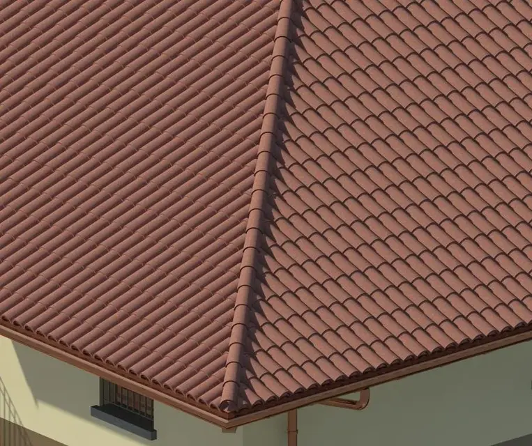
I'm still sorry to bother you, but I have another problem, after I put the tiles as I extend them to the tiles of the other layer? I attach a photo so it is clearer, thanks a thousand
In my opinion, the problem lies in the tiles placed on the displacement line. If you read the posts back it happened to me something like that. if you try to change a bit the offsets of the tiles on the spread should extend the tiles on the ground.
the spreadsheets always put them after as a single beam and as they place on the level of others you have to change the odds of the extremes
usually around + 8 cm compared to the quotas of the tiles on the ground
I have two questions to ask you:
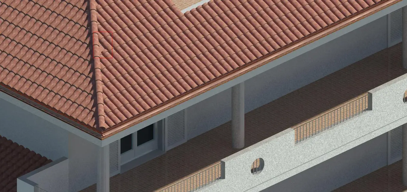
1 When I make the system of beams a beam of plugs comes out shorter and even in the other layer to what is due? ?
2 x render54: how do I bring the color of the hoods like yours?? and not so much numbed? ?
...and take it well armored, because r2011 you dust the ram and the cpu! the more you put it and the better it is! and for the future I don't think that things will improve, indeed... there is already i-ray (motor rendering) on 3ds max, who knows that in the 2018 version comes also on revit!:biggrin:
Excuse the ot.
at home I have a 32-bit qcore, 2.4 ghz with 4 gb ram I activated the revit home license 2011
Stop!
2010 went great on the same
where
64 bits, i7 and at least 8 gb ram
a few days ago I found this site http://3dws.net/made specifically for graphics
") thank you very much.
thank you very much. Will it affect when I make the renders?
") now I should take a new computer then I update
now I should take a new computer then I update