• This forum is the machine-generated translation of www.cad3d.it/forum1 - the Italian design community. Several terms are not translated correctly.

table reduce epicicloidal

I wanted to ask you one last thing: according to you is necessary a tolerance of flatness (and/or a narrower roughness) on the right side of the plate on which the shouldering of the pin rests before the entrance to the conical hole?
I would not put either of them, being a worked plan; here however you should think what will be the initial state of the crude and how this piece will be worked.

I would also have great perplexity to maintain both the pin and the conical centering because as already mentioned in the case of the centering, it will be difficult to make them work at the same time.
personally on this side I would prefer the bar and the cylindrical pin; In this way you can lock the screws by axially blocking and centering the pin by pressing it on the right conical part. However, the problem of the 12h7 centring remains with the pin of the counterpiece that touches in the head.
- I think I understand what you mean in the third point, but I don't know how to solve the problem: the conical hole I need for connection between the left plate and the pin that supports the hammer holder, while the other hole is necessary to connect the left plate with the right plate of the hammer holder and therefore designed to ensure greater stability.
You could solve in this way: the ends of the pins and relative seats the cylindrical dots, I would shorten the right counterpiece so that you can apply a screw at the head of the pin (left) to prevent it from slipping while its position is maintained by the already present bar. in this way you can go to line with the centering 12 h7.
 
I would not put either of them, being a worked plan; here however you should think what will be the initial state of the crude and how this piece will be worked.

I would also have great perplexity to maintain both the pin and the conical centering because as already mentioned in the case of the centering, it will be difficult to make them work at the same time.
personally on this side I would prefer the bar and the cylindrical pin; In this way you can lock the screws by axially blocking and centering the pin by pressing it on the right conical part. However, the problem of the 12h7 centring remains with the pin of the counterpiece that touches in the head.

You could solve in this way: the ends of the pins and relative seats the cylindrical dots, I would shorten the right counterpiece so that you can apply a screw at the head of the pin (left) to prevent it from slipping while its position is maintained by the already present bar. in this way you can go to line with the centering 12 h7.
I understand, thank you very much. In any case, I thought I would draw the milling piece from a cylinder of 12 thickness and 90 diameter (using numerical control machines?). sincerely seen the complexity of the piece I do not see many alternatives. I ask for one last confirmation on the choice of the datum d and in general on the correctness of the various tolerances, at least in case I correct what is suggested to then print the drawing.
 
I saw the last drawing. already much better than the first.1711571223949.pnghere puts a 3x in front of the designation of the hole (even in the other).
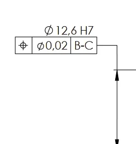
you do not have to put b-c, but b in one box and c in another box.
 
I saw the last drawing. already much better than the first.View attachment 70812here puts a 3x in front of the designation of the hole (even in the other).
you do not have to put b-c, but b in one box and c in another box.
Thank you very much, I have already corrected everything. I ask confirmation of the choice of datum (especially d; is it necessary or is it better to always consider c as reference for perpendicularity?). according to you it is necessary to add some other dimensional/geometric tolerance or roughness (such as flatness on the surface where it beats the shouldering of the tree) or the design is all summed up already complete? in the case between tomorrow and Friday mold the two drawings.
 
I ask confirmation of the choice of datum (especially d; is it necessary or is it better to always consider c as reference for perpendicularity? ).
I would choose b as datum with parallel tolerance, as it is easier to control. I would eliminate it.
according to you it is necessary to add some other dimensional/geometric tolerance or roughness (such as flatness on the surface where it beats the shouldering of the tree) or the design is all summed up already complete?
I would say that it is important to define a flatness for the surface b.

I've seen that you put general tolerances in your cart. iso2768 was replaced by iso 22081.
 

Forum statistics

Threads
44,997
Messages
339,767
Members
4
Latest member
ibt

Members online

No members online now.
Back
Top