• This forum is the machine-generated translation of www.cad3d.it/forum1 - the Italian design community. Several terms are not translated correctly.

turn dicom files into stl and then reverse on cad

  • Thread starter Thread starter jno
  • Start date Start date

jno

Guest
Hello to all of the forum.

:smile: I ask if there is a possibility of exchange favors on bares or around.

I leave from (under) zero....
I can scan high resolution of objects up to 45x45x100 cm practically every day.
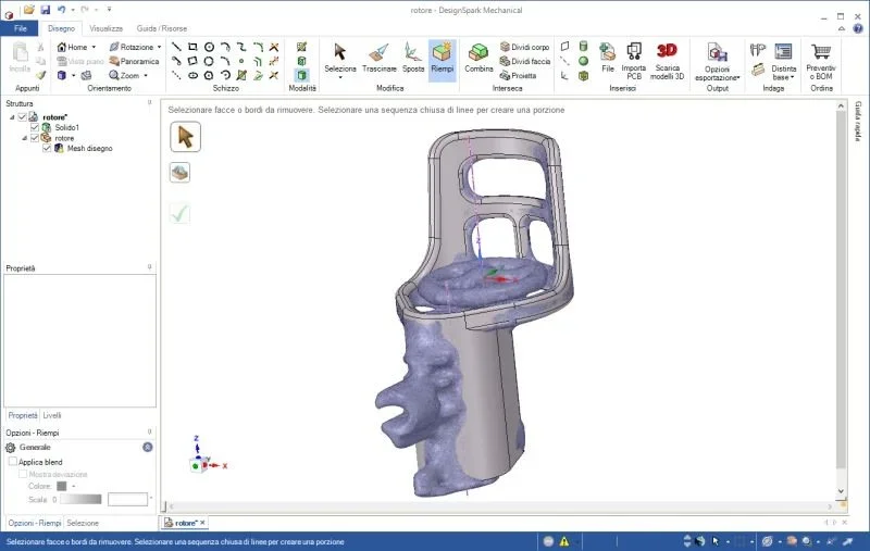
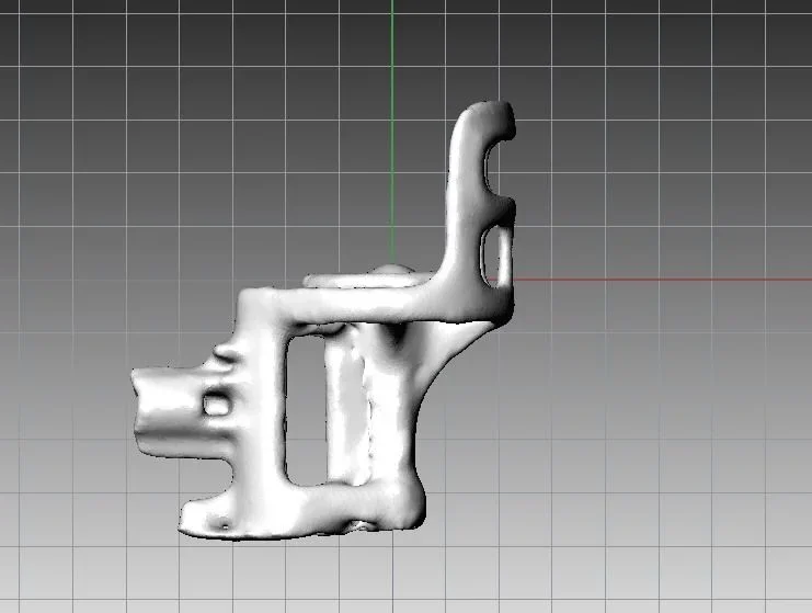
being at first I tried to make smart and convert a plastic object from dicom to stl
to be able to import it into a cad to vary its measurements, this is what I need.
(The object is disarming simplicity, but my ignorance of the newly downloaded programs is not just: )

x-ray scanning allows to have also the inner part scanned objects,
Usually you search this feature for mechanical objects.
monthly I can also perform unusual scans of 55x55x200 cm depending on weight.

in the first test I used an acquisition with these parameters:
80 kv, 30mas, 64 x 0.625 mm per slice, 5x5 cm of fov, in pure axial
with noise reduction metal parts (the object has a metal shaft)
and reduction of noise during reconstruction of dicom images
owner of the equipment I assist.

the resulting dicom file travels on the 185 mb and the stl file on the 150 mb, but it is precisely on the conversion that I have problems,
I have to generate a decent file to send to any press center.

the exchange I propose would be to perform scans for those who need it
and receive appropriate instructions on the use of 3dslicer for the correct conversion to stl.
(I also downloaded meshlab, meshmixer and designpark)

Moreover, finding the correct parameters and steps also serves to those who then ask me for scans.
(you will find yourself with the same problem )

I can always monthly increase scanning quality to 0.3 mm slice in pure axial
or down to 0.1mm in volumetric acquisition.

:smile: Hopefully I guessed the right section I expect some constructive response
Of course I can attach photos of the object, what it takes etc.

p.s. to the fans: have mercy on my ignorance, I would like to learn.
 
:smile: that in the image at the top right is the toy drone carriers
the upper left is the excavation under tac of the previous piece in dicom, translated into stl

in the central part of the image the addition of a hand-made mower
with the two-component, blurred compared to the original 60° engine
and under the block with the two motors and the mounted propeller.
wyn5.jpg
at least scan on tac of the piece and conversion to stl is decent?

having never worked in this field and in so little time,
I have no idea if I'm doing well,
or I'm completely wrong approach...:confused:
 
:rolleyes: Nothing to do, I have tried all the sauces, I understand that improvising a change
It can't be simple, but...
rcmsya.jpg
some rocks:
- stl files are not geometrically editable
(e.g., I just want to move the cylinder drive cord)
are only printable, at the most scalable (big or reducing all the object)

-if I want to use the stl file as a base to build it inside and around an object in cad 3d,
being the stl file of the object not perfectly in the plane, they are problems.. :
(I can't turn it on that couple of degrees it would be necessary to play it with the cad)

I hoped someone could use x-ray scans
and exchange the favor of the change of info,
Moreover it is not possible to think that someone spends a figure that starts from over 200,000 euros
up to a million euros for a scanner that also eliminates the noise introduced by metal parts.

the cost of the object is less than 2 euros (it is a toy), are about 5 cylinders and a couple of floors.

I attach a conversion of the object, from 180 mb I managed to descend simplifying the file
up to get 8 mb zipped.www.dropbox.com/s/zfy7g30pv1uc8uo/motor2.rar?dl=0in short I also tried to educate myself and try alone,
but starting from scratch is really hard.... .
(also tried a conversion program from mesh to nurbs,
after 24 hours I had to fear it, it does not work ):confused:

:redface: Is anyone looking at us?
 
-if I want to use the stl file as a base to build it inside and around an object in cad 3d,
being the stl file of the object not perfectly in the plane, they are problems.. :
(I can't turn it on that couple of degrees it would be necessary to play it with the cad)

:redface: Is anyone looking at us?
as mentioned above,
I want to rebuild it alone with the designpark,
if only I could understand how you change some degree the reference plan of the stl file,
so that if I make a "cut" of the object this is parallel or perfect squadron
and not as you see in the image with a cut that dissects him badly
while having requested 180° precise
jhu075.webp
 
as mentioned above,
I want to rebuild it alone with the designpark,
if only I could understand how you change some degree the reference plan of the stl file,
so that if I make a "cut" of the object this is parallel or perfect squadron
and not as you see in the image with a cut that dissects him badly
while having requested 180° precise
Hi.
I can't help you in advising the right parameters to set in the equipment you use, as I'm just an optical scan user.

the file you have attached is practically useless for the purpose of the "precise" reconstruction of the object being too little detailed.
possible causes:

1) maybe you exaggerated when you converted the scan to stl, setting the decimation conditions of the triangles too striing. The result is a very "light" but useless file.

2) maybe the size of the object is too small and the parameters set on the scanning machine suitable for larger objects.

Try to post an image of the object originally scanned by the tac, so we can figure out which of the two assumptions corresponds to reality.

as much as you look at the software you mention (designspark) I can't tell you which commands to use to move the stl.
 
:biggrin: hello is thank you again for the answer.

:confused: according to your experience, you just cannot turn a thread the object con meshlaband fix the stl file with this new reference plan?

I send you the file of a step made before the push simplification,
the forum allows to attach only up to 20 mb:
https://www.dropbox.com/s/x6og6sxs8mjvuvl/tissue.rar?dl=0(that of the step still preceding is 155 mb)
 
is a bit the limit of free applications.
with geomagic (and with other applications such as rapidform or polyworks) the correct repositioning is done quietly.
 
Yeah, I see.

:frown: I don't want to play dirty and install crakkate versions.
which then bring you tons of "monnezzware" below to do this.
those I have are free and downloaded from official sites.

if with designpark I insert a simple hollow cylinder in the pilot mesh image
it is clearly seen that the object is out of axis, even if in phase of acquisition on the tac
I had tried to place it in a squadron and at isocentro, I would say that I was rude to position at least 3rd.
Immagine.webp
 
according to your experience, you just cannot rotate a thread the object con meshlaband fix the stl file with this new reference plan?
I don't usually use meshlab, so I can't answer. I positioned and aligned your first stl using rhino3d.
( find the attached file )


I looked at the second file you attached. I'm afraid you did something wrong with scanning.
the file although having 4,326.006 vertices is extremely rough, as if the step on the axis z was excessively wide (0.6mm).
also decimating the cloud of points and trying to rebuild it I fear that the result would not be better.
You should study the manual of your equipment to understand how to use it at best... other not recommended.

[Bleep]
edit: cad3d.it does not complete the upload of the .rar file that contains the stl positioned, accepted only the image
I don't know what it's like, both firefox and chrome have made cleavage.
[Bleep]
 

Attachments

  • img1.webp
    img1.webp
    15.9 KB · Views: 5
:smile: exact, in z axis the acquisition slices in axial scanning are from 0.625 mm

already your observation is very useful, because the acquisition can be set
from axial to volumetric with thicknesses from 0.1mm, I have to do it again so. :finger:
 
I'm just going out a post.
It's a little long to explain, you're a little sorry.

I need to settle the grandchildren of 10 and 5 years of which to the greatest
I had the unfortunate idea of giving 3 months ago a toy quadcopter, a drone.

like every uncle who respects, I can't say no to the grandchild
who still wants to use her.
So I had to take away everything I had buried as a kid.
and that I knew how to do on the first radio remotes in the 70's
and apply it to the needs of the grandchild.
(including updating me on this new technology, chips included)

so I had to study the mechanical operation of quadcopters,
reverse engineering of the electronic remote control scheme,
(of course on the net the scheme is not there, we talk about 69 euros toy, the spare parts cost a tot per kg)
and build a modified one that limited the flight in height and slowed its movements for the child.

then the niece realized that so modified has an almost perfect hoover,
and he could make shots for "selfies"
(a fashion that I understand little, maybe age.... )
then I had to waterproof the parts so land in the pool and leave
(and there the selfie not? :
now I'm finishing the variations to let it navigate under a few centimeters of water
(radiofrequency does not allow immersion control)
and I replaced the lipo battery to increase the flight from 5 minutes to a good quarter of an hour.

If you want to laugh, the engines last up to 2-3 hours of use combined
and since I supplied them with batteries from 15 minutes or more, I must then replace them 2 times week
and those faults I have to repair them with the magnifying glass. . .

now also want the videocamerina fvp vision on the real time mobile of the flight
that costs yes little (39 euros) but weighs 100 grams and I had to vary
the plastic block that brings the engines to increase its power... .

doing this last thing by hand was not simple, 2 hours of hand-to-block work (it is 4). .

the intention was then to translate these 2 cm plastic into a 3d design and then vary
the distance between the mechanisms on the computer so as not to inflate the external dimensions
and let them return to the original chassis
(oops, they corrected me at the shop, the chassis is called canopies, costs 9 euros )

I realize that, perhaps wrongly, I entered a forum where I read
of fior flower of professionals, I hope at least that the acquisition under tac apparatus
may sooner or later affect the professional side of the forum and
compensate somehow how much you are giving me in suggestions.

ps: I did not put toy brand and model, I do not know if it is allowed,
if you have kids or grandchildren to whom you want to provide a drone toy,
I share the last 3 months of research on this
(schemes, modifications, tricks, repairs etc.)

an example of the potential of these toys:https://www.youtube.com/watch?v=tfe3t0u3j-8
 
an example of the potential of these toys:https://www.youtube.com/watch?v=tfe3t0u3j-8
For a while, I've had the idea of buying a drone for some video.

Then I realized that in order to have something semi-professional (go-pro, stabilizer and drone with autonomy of 20-25 minutes) I should have spent a small fortune...too much for a whim:biggrin:

The drone you used for youtube shooting is the one in the image I attached? (syma x5c)
the images of the sunset of messina were made with the video room supplied to the drone (the one from 2megapixel) ?

Is there a way to stabilize the shooting or the drone is too light and affected by wind turbulence?
 

Attachments

  • SYMA X5C.webp
    SYMA X5C.webp
    18.7 KB · Views: 58
, is he, the syma x5c-1 , which means a package with
drone, 5 minute flight battery, remote control, 2 mpixel camera recording on sd card,
to the incredible cost of 69 euros from Italy (and even less from the cina)

As you can see, my nephew's is a modified thread:
-modifies antennas, for a minimum of 100 mt of commands
- battery from 1800 mah and 65c, from 20 minutes of continuous flight,
and glued to the "tape" of the battery/porttelecamerine drawer, waterproof connector
-the camera was placed inside the drone and silicone insulation (waterproof)
- the receiving circuit has been painted with the insulation paint transformers,
can be immersed in water
- scooters have been made waterproof with a drop of fat to the teflon within each engine
and can be immersed in water
- replace the original 36000 rpm scooters with the most performing 48000 rpm
- added filters that protect the mechanisms from grass, wires, stones and other
- radio control over slow motions for shooting

the total weight rises from 80 to 120 grams and makes it more stable to the wind.
dpth60.webpwith this additional necessary modification of the double motors we climb to 180 grams,
included the new fvp telecamerina that connects to a mobile phone or to any laptop
it will be settled at the end. :tongue::wink
 
if you want good results on filming
and you are not pleased to make mechanical / electronic modifications to the drone
the choice for a system that is worth everything that costs
It is only this:
http://www.gearbest.com/rc-quadcopters/pp_227349.htmlthere is no better at equal costs,
to improve these characteristics only a few percentage points buying other systems and brands spending doubles and touches 500 euros


while in order to make all those changes to the grandson's drone,
without having to subtract his for tests and functional checks,
I used syma x5c spare parts purchased in advance and got
a car drone built with 48 euros, all the pieces remain useful for
repair the niece's, nothing's going on.44cm.webpwith this method I learned the basics for proper functioning of drones in general
after only three months I can help people who have bought it already beautiful and ready for years
They couldn't see how to solve certain problems.
the saying "an example is worth more than a thousand words" is the one most corresponding to reality

:smile: please, the second stl file that I attached in the thread,
If you can change it in plan and square, then send it to my mail?
[email protected]because the forum does not allow to attach more than 20 mb, unfortunately.
 
:redface:I couldn't straighten the stl file,I thought I cut a slice of 2 mm
so that the cable cylinders to be inserted inside You don't seem too foolish
2ppylxi.jpg
it starts, but part nastyrello strong :rolleyes:
, however the distance of the two engines
compared to the main gear it was possible to move the three cylinders,
in short in the original form it is possible to insert them
without cumping out as in the hand-made experiment with two-component glue.

:tongue: using a thread of optimism, maybe by the end of the year I can finish it.. . .
 
:redface:I couldn't straighten the stl file,I thought I cut a slice of 2 mm
so that the cable cylinders to be inserted inside You don't seem too foolish it starts, but part nastyrello strong :rolleyes:
, however the distance of the two engines
compared to the main gear it was possible to move the three cylinders,
in short in the original form it is possible to insert them
without cumping out as in the hand-made experiment with two-component glue.

:tongue: using a thread of optimism, maybe by the end of the year I can finish it.. . .
look that such a detail can be reconstructed even without resorting to stl.
It is enough to arm itself with a good digital caliber and detect measurements, paying attention (as precision) only to areas that need to be precise.
If I had to do it in rhino I would act like this:
1) taking some pictures ..sopra and side to seize all the details.
2) importing the photo in rhino and climbing it having as reference some measure known.
3) tracking reference curves directly on the photos.
4) from the curves ... building the math of the piece

The image I attach is the model of a drone I built the surfaces in the manner described.
Unfortunately not having the physical object available, the measures are certainly not correct, but being a modelling exercise ... I am satisfied :frown:
 

Attachments

  • drone-2.webp
    drone-2.webp
    35.3 KB · Views: 9
:eek: uhe the patch... looks like a photo, and less bad that is not accurate.:rolleyes:

My problem is that it's all new, for every single step I have to find the tutorial, listen to it and understand it,
then create the union between two lines, and not always works because the tutorial is
was made on previous versions, often do not match the keys :frown:

you probably wouldn't even take 5 minutes to remake the attached stl file in cad.
the problem is that I have nothing useful to trade. . .
I have a chance to do scans by tac, but there's no one in the area,
I can indicate how to change patterns and where to find spare parts of the toy, but if one has no children interested,
another old hobby is numerical compression, numerical matrices, you call jpeg, mpeg,divx etc.
and worldwide I have published twenty records, but also to use them in another way
who manages the numerical games is not broken, in the end it is stuff that only helps the receivers against the robberies and/or similar problems. .

I can certainly not buy rhino to rebuild a single piece of plastic, it is not and never will be a job for me.
but remains a fascinating world, at least the satisfaction of making the object, let it print
I want to finish it.

thanks again for the patience and indications :smile:
 
I downloaded mechanical designspark to try to give you a hand but... It seems that the solid I imported is blocked and cannot be changed.
designpark seems to be a very simplified version of spaceclaim, in fact the online guide that appears (pressing f1 ) is precisely that of spaceclaim.
 

Attachments

Last edited:
:finger: but... it's beautiful! :biggrin:

If I read the bottom, can I "set up" the modified one I did, to change according to the engines?
I hope so.
Sorry the "photomontage" crude, corresponds to the piece that I designed and that I will adapt to the top that you designed,
This will work:
wlafza.jpg
4mmx12mm motors reach 86000 laps and weigh 1,2 grams each,
I can also mount six together, wanting it.

:It will become the fastest "game" in the world.

I work them tonight and join them, I think I should have finished and put the file back for tomorrow.
and if you confirm that it is printable I find a press center near home and I make them do.

If everything goes well, this is the time I have to learn how to post a movie on youtube
to do two tests:
take-off normal toy from ground up to a floor x of a palace and its seconds
and take-off toy modified in the same conditions and possible improvement of the times.

then adopted the modified block with the most suitable engines to bring
the videocamerina fvp and accontent finally nipotame

Also if I look for space claim tutorials there are in bizzeffe, I didn't know it came from that program the desigspark.

Thank you very much, as soon as I can place the results
 
Hi, I can't do anything about the design, the program indicates that it's stuck.

it does not unblock in any proven way. :frown:
I tried to copy the top to paste it to what I drew, but it's not even possible that way.

you can't even add a solid by sticking it on what you posted to me,
but if it is physically detached it adds it.

on the tutorials says to save an unblocked copy, on the card runs it and creates the file
but this file once loaded is still blocked.

Do I have to do some special operation? :confused:
 

Forum statistics

Threads
44,997
Messages
339,767
Members
4
Latest member
ibt

Members online

No members online now.
Back
Top