Join the forum for Designers!
Your expertise is vital to the community. Join us and contribute your knowledge!
Join the Forum NowShare, learn and grow with the best professionals in the industry.
Global processing systems manufacturer streamlines workflows with iLogic and FDU
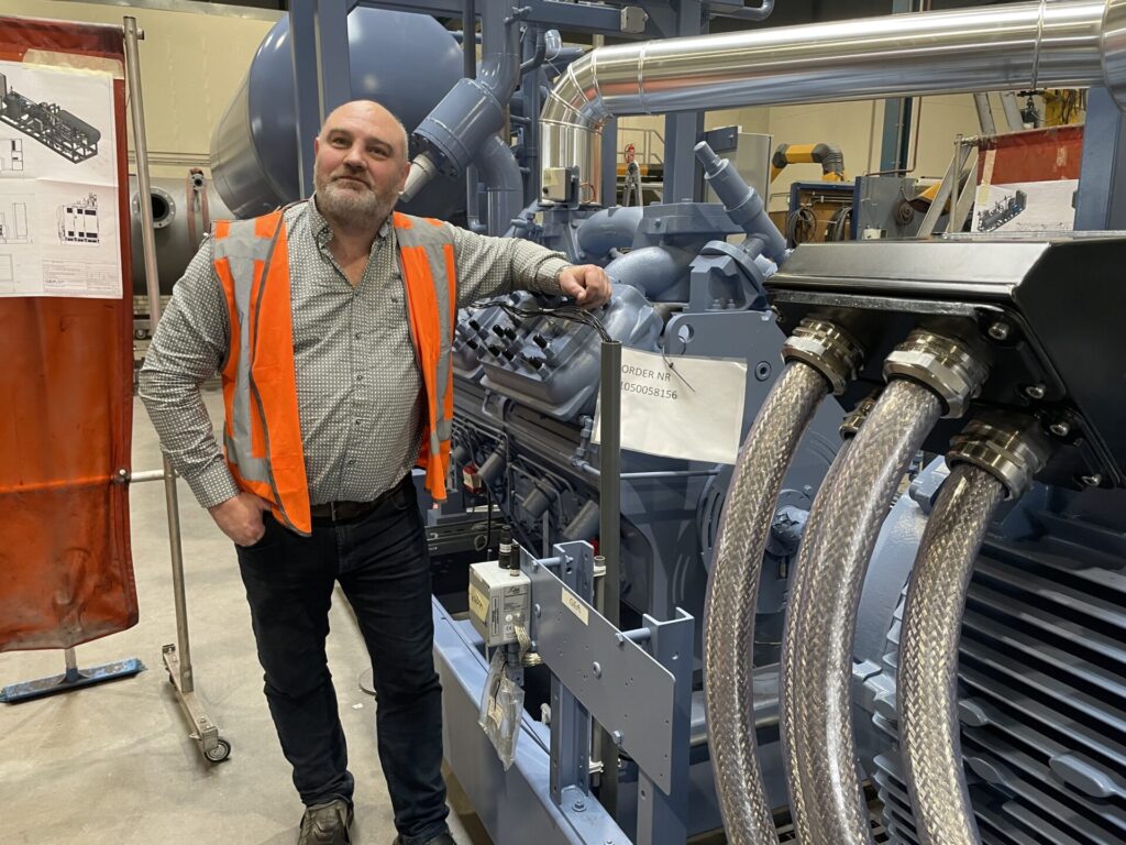
As one of the largest industrial processing systems suppliers in the world, Dusseldorf, Germany-based GEA makes the machines that make the products we use every day, from the foods and beverages in our grocery carts to the medicines our doctors prescribe to the gas in our cars. These include both standard systems and custom, made-to-order solutions.
The latter are developed with iLogic, a specialized set of tools within Autodesk® Inventor® based around rules-driven design.
Large-scale processing systems use many of the same types of components—compressors, pumps, valves, controllers, mixers, homogenizers—in unique configurations. The iLogic tools allow GEA engineers to create a “parametric skeleton” that standard product teams can then adjust to create new models automatically.

“We meet regularly with the experts who understand all the intricacies of a specific process and the GEA machine for that process,” says Lune Riezebos, Application Specialist in Service Delivery with GEA. “They explain what parameters they have, and that’s all we need to build a model that they can adjust and turn into many different configurations automatically.”
Over time, this creates a library of components that can be repurposed many times over, developing standardized products for custom scenarios without going through a lengthier, more traditional customization process.
“We can create a new model in 2 hours instead of 3 weeks,” Riezebos says. “Depending on the complexity of the system, they can cut engineering time anywhere from 30% to 80%. That makes it much easier to meet customers’ needs.”
But the company soon realized its new approach came with an unexpected challenge.
The sales cycle for large processing systems can be long because the customer and GEA are figuring out how to solve a new problem. At the same time, GEA must use its engineering resources wisely, so it was not always possible to develop a complete 3D model of a solution before the customer signed the contract.
To bridge the gap, sales teams were developing 2D layouts with AutoCAD® during the initial phase of the sales cycle. Engineers would then recreate these layouts in 3D with Inventor after the sale was confirmed. This resulted in a great deal of duplicated effort. It also created some uncomfortable situations when the sales team inadvertently created 2D system layouts that could not be manufactured as specified. This was an unanticipated result of well-intentioned sales teams responding to customer requests for changes before the engineering team became involved.
“We had worked out a way for the sales teams to build systems by putting together ‘blocks’ in AutoCAD,” says Martin Andersen, Senior Manager Design Engineer for GEA. “But it was too easy to change aspects that shouldn’t be changed. When we reached the project phase and began redrawing everything from scratch, we had to tell the customers that what they signed off on could not actually be done.”
While Andersen’s team could always amend the 3D layout to meet the customer’s needs, the disconnect brought unnecessary tension and delay into the process. That’s when the engineering team realized a much more efficient method was already available in the Autodesk Product Design and Manufacturing Collection.
As it turned out, the answer was Factory Design Utilities—only available in the Product Design and Manufacturing Collection. It can link 2D layouts created in AutoCAD with 3D models. In other words, Factory Design Utilities allowed the GEA team to create 2D and 3D layouts simultaneously and keep them in sync with every round of changes.
See how this realization not only helped GEA dramatically reduce the time involved in 3D layout production but also make the entire sales cycle more efficient.
Join the forum for Designers!
Your expertise is vital to the community. Join us and contribute your knowledge!
Join the Forum NowShare, learn and grow with the best professionals in the industry.

