ValveFloyd
Guest
Good morning to all,
I am a student of the first year of mechanical engineering and I am preparing the drawing exam. I am encapsulated in this overall on which I have several doubts. I ask that unfortunately I cannot request a reception to the professor and therefore I address myself to you experts.
My doubts are:
Christian


I am a student of the first year of mechanical engineering and I am preparing the drawing exam. I am encapsulated in this overall on which I have several doubts. I ask that unfortunately I cannot request a reception to the professor and therefore I address myself to you experts.
My doubts are:
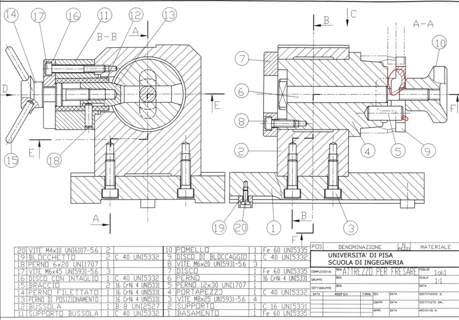
- interpretation of the operation and use of the object. in particular I think I have been able to guess that somehow it is used as a carrier or support (which flows on a guide thanks to the 19 blocks) for some milling operation and, in particular, it blocks the rotation of the pin 6 through the scrolling of the pin 14, however I do not yet have a clear vision of how it is used specifically
- longitudinal position of the subgroup formed by the components 11, 16, 14, etc... I would have imagined it placed in correspondence of the dotted lines circled in the second photo, however I do not return then the position of the section plan b-b. or perhaps it is some regulatory compromise to reduce the necessary views and at the same time fully represent the object?
- I do not understand the absence of bronzine and/or lubrication between pin 6 and body 4. I agree that the spin of the pin is slow and salty, but I am not entirely convinced of the goodness of the design choice.
- the presence of the staircase circled in the third image. I guess she doesn't have a functional role. I can assume that it has only been realized to make the geometry of the subject a little more complicated.
- size and function of pin 5
Christian
Last edited:
")