• This forum is the machine-generated translation of www.cad3d.it/forum1 - the Italian design community. Several terms are not translated correctly.

design with spaceclaim

  • Thread starter Thread starter SimoneDB
  • Start date Start date
Yes, unfortunately the passage from 2d to 3d is always a bad blow initially. There are 3 things that generally convince those who then decide to move from 2d to spaceclaim:

1)After designing a small set (and so far they say "nice, but I would have been the same time with acad"), I show him that the table is automatic (ooh! we now give it for granted... but they must make projections! )
2)I show him that if I change one or more particular these are updated also in the table and in the developments
3)I show him that, taking some old 2d files, these can be updated by giving a third dimension, so as to make them reusable as components for new models... ah and so I can also calculate the weight of the piece (ooo!)

Of course I can't imagine how it is to design a total of 3d in 2d, there have never been, and probably many of us subscribed to cad3d obviously give for granted the things mentioned... The only obstacle I find in general is the fear of having to learn how to use a new cad, or rather a new system to design. . . many feel inadequate (they look like the mouse to the nail). But I think, though sc is a 3d, he approaches very much like sketchup to a 2d with a third dimension. many things (e.g. holes, sunshades, pockets, bevels, fittings) you can draw them exactly as you did before with acad.
 
Andrea, now I'm curious, I've never seen a video of sc regarding tubular frames and sheet metal... Is there anything on the internet to see?
 
mmm a little something, but if you give me a file made with sw I try with sc and make you a video.
I still haven't been able to search. now I have another curiosity: when on a particular sheet I have two different bent rays, type 1.5 and 50 can manage two different values of factor k? (I understand 1.5 as a typical radius and 50 as a coniatura fold radius with a round of 100, or a centimeter radius that definitely has a different k value)?
 
I still haven't been able to search. now I have another curiosity: when on a particular sheet I have two different bent rays, type 1.5 and 50 can manage two different values of factor k? (I understand 1.5 as a typical radius and 50 as a coniatura fold radius with a round of 100, or a centimeter radius that definitely has a different k value)?
yes, the factor k is treated in a variable way: part from a value (let us assume 0.28) for r=thickness and it becomes 0.5 as we loosen (e.g. r 100 has definitely a k factor of 0.5 as in lattoneria). However, you can work on fold tables (as opposed to k factor) which allow (even at equal radius) to select a different matrix (v-die).
 
[video=youtube_share;eCm2vYsHTxc]http://youtu.be/ecm2vyshtxc[/video]Here we go. for simplicity I started from the 2d sketch with the exact measurements, but I could have drawn two rectangles any and then mofy the size easily so as to get what I wanted. if it is useful I can make a video about how to place two frames with incorrect size or how to place them. I can also complete the video by entering the lock. Is it to be integrated?
 
[video=youtube_share;eCm2vYsHTxc]http://youtu.be/ecm2vyshtxc[/video]Here we go. for simplicity I started from the 2d sketch with the exact measurements, but I could have drawn two rectangles any and then mofy the size easily so as to get what I wanted. if it is useful I can make a video about how to place two frames with incorrect size or how to place them. I can also complete the video by entering the lock. Is it to be integrated?
the video is very clear and exhaustive...I actually thought there was a toolbox like on solidwoks. this is a simple extrusion of the profile, although then it turns everything into table on the cartilage! I think it is not very important to add the lock to the video, possibly changing the size of the frame to bring it to correct size (at least you do not use the usual methods of other video type drags and moves... )
p.s. gorea I am a curious, you actually know it yourself if you need to integrate it or not!

Good day and thank you.
 
...I actually thought there was like a toolbox on solidwoks.
would the toolbox be a library? you have 2 online: cadenas and tracepart. both have an integration with spaceclaim. If you want (and this is interesting) you can save the components in folders and create your "toolbox"... the spaceclaim file contains a thumbnail and preview in windows (without opening the program) shows you in 3d the piece. for insertion you can press "insert" or drag the file.
clearly when imported a profile (e.g. length 1m) you can resize it (with drag or move) and cut it with planes or rotations of the faces.
I think it is not very important to add the lock to the video, possibly changing the size of the frame to bring it to correct size (at least you do not use the usual methods of other video type drags and moves... )
Yeah, that's how it works. However, once you do, you can create a parametric model (where you set the size in excel for example)[/QUOTE]
p.s. gorea I am a curious, you actually know it yourself if you need to integrate it or not!
no, instead I find it useful to ask why I do not know the other systems well (some yes, but for heads) and I do not know what idea can be made of spaceclaim. I give for granted a lot of things, and I don't know what you know or what you get. I think I could add a model (like a lock) and size it by adapting it to the model already made. so we see how you adjust the size and you place (transport moves as you already imagined), but also the online and local library (autoproduced with windows folders).
 
would the toolbox be a library? you have 2 online: cadenas and tracepart. both have an integration with spaceclaim. If you want (and this is interesting) you can save the components in folders and create your "toolbox"... the spaceclaim file contains a thumbnail and preview in windows (without opening the program) shows you in 3d the piece. for insertion you can press "insert" or drag the file.
clearly when imported a profile (e.g. length 1m) you can resize it (with drag or move) and cut it with planes or rotations of the faces.

Yeah, that's how it works. However, once you do, you can create a parametric model (where you set the size in excel for example)
no, instead I find it useful to ask why I do not know the other systems well (some yes, but for heads) and I do not know what idea can be made of spaceclaim. I give for granted a lot of things, and I don't know what you know or what you get. I think I could add a model (like a lock) and size it by adapting it to the model already made. so we see how you adjust the size and you place (transport moves as you already imagined), but also the online and local library (autoproduced with windows folders).[/QUOTE]as regards toolbox is the library of "schizzi 2d" profiles to be extruded. solidworks has already integrated them and can create personal ones. regarding spaceclaim I agree on this new future video. definitely is something new, never seen on the net on youtube!
Thanks for the interest, rotten.
 
would the toolbox be a library? you have 2 online: cadenas and tracepart. both have an integration with spaceclaim. If you want (and this is interesting) you can save the components in folders and create your "toolbox"... the spaceclaim file contains a thumbnail and preview in windows (without opening the program) shows you in 3d the piece. for insertion you can press "insert" or drag the file.
clearly when imported a profile (e.g. length 1m) you can resize it (with drag or move) and cut it with planes or rotations of the faces.

Yeah, that's how it works. However, once you do, you can create a parametric model (where you set the size in excel for example)
up...

I also saw that in the sheet metal department there is a "card" function.... what is it?
 
Wait, I lost... What was there to show? the toolbox? I don't remember.

with regard to the "sketch" by selecting a live edge (where there might be a fold to understand us) we can create a series of "cloths" between one side and the other of the sheet. is an alternative way of "shaping" and then close a sheet.
hi andrea, I was referring to the toolbox you told me was external to spacecliam... I don't remember the speech, but I'm curious now!
As for the "schedule" function, I'm curious because in sw it doesn't exist (at least on the "my" 2012)... can only be treated the edges of the sheet or the sheeting make me even half a piece? Do you treat it on the multilamiera or in the environment together?

Thank you, Marco.
 
Wait, I lost... What was there to show? the toolbox? I don't remember.

with regard to the "sketch" by selecting a live edge (where there might be a fold to understand us) we can create a series of "cloths" between one side and the other of the sheet. is an alternative way of "shaping" and then close a sheet.
hi gorea, I remember that several years ago I saw a video where you "copy" the internal or external walls of a piece imported on spaceclaim and turns it into surface, then give it the right thickness and turn it into sheet metal... How does it work and what is it for?
 
hi gorea, I remember that several years ago I saw a video where you "copy" the internal or external walls of a piece imported on spaceclaim and turns it into surface, then give it the right thickness and turn it into sheet metal... How does it work and what is it for?
Hello, Marco.
copy a wall and drag it to the thickness necessary to rebuild the sheet properly. As you know, there must be a constant offset throughout the surface. If there are hollow holes, bevels, or non-consistent rays (thickness 1, inner radius 1, external radius 3, for example) dragging the surface (drawing the correct one) all these "errors" are removed and you get the part to be cut.

Besides, it is an excellent separation tool. I'm sending you the video I made for a client on his piece.
all this is fantastic, I don't think there is on sw, at least not as fast as command! beautiful!
returning a step back, the tab function (also not present on sw) works only within the same part or even together between different pieces? Is it also just a type of "corner treatment" or can you do with command also on the center of the piece?
Thank you in advance, Marco.
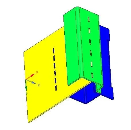
card works as junction (as fold and other), but if you have a sheet that goes on itself (also in the center) you can create a tab, as long as the terminal face touches a flat part. can be part of an assembly in the sense that the sheet component can be decomposed into several parts of the same thickness and in this case the feature remains parametric.
in my example 3 parts (3 colors) with different tabs
Capture.webp
 
card works as junction (as fold and other), but if you have a sheet that goes on itself (also in the center) you can create a tab, as long as the terminal face touches a flat part. can be part of an assembly in the sense that the sheet component can be decomposed into several parts of the same thickness and in this case the feature remains parametric.
in my example 3 parts (3 colors) with different tabs
View attachment 40633
excellent the function "scheda". Today, after lunch, looking at youtube I wondered how to approach the drawing of sheet metal together with sc. or better, when there are complicated or inclined pieces mounted together and you need to make changes, how does sc behave? I with sw go fishing the function, various quotas and magically corrects the piece and asses with all the details connected....
I think it's different, I don't know if better or worse. I'd like some disappointment, please. (I'm as corious as monkeys... )
 

Forum statistics

Threads
44,997
Messages
339,767
Members
4
Latest member
ibt

Members online

No members online now.
Back
Top